Showing posts with label Robotics & Automation Engineering Journal. Show all posts

Monday, 27 March 2023

Lupine Publishers| Avoiding Vulnerabilities and Attacks with a Proactive Strategy for Web Applications

Lupine Publishers| Journal of Robotics & Mechanical Engineering


Abstract

As the number of users interacting with dark websites grows, it opens the door for vulnerable and malevolent actors, making web traffic unsafe and risky. To prevent such vulnerabilities and maleficent activities on dark websites the proactive strategic measures have been taken into account and the relevant hidden causes are explored that helps to overcome the security risks during various web operations. In the first step, from the dark web corpus, the web addresses have been analyzed to check the status of whether these web addresses are available or not. To prevent the web addresses mining challenges a script was designed to mines irrelevant web address URL by visiting multiple search engines based on user input. In the 2nd step, another script was designed to check those domains having chances of becoming inactive because for security reasons such as onion sites. In 3rd step, various gape has been identified in dark web hosting using crawls that create the new links from configuration files. In the 4th step, using manual and automated testing the maleficent activities were identified in web traffic. Further proceeding to the 5th step, the web address lifespan was determined which quantifies the duration between the first and last occurrences of a web address. Finally, using Fisher’s Exact Test (FET), two comparative scenarios have been developed by considering the similar attributes and the role of operating system interaction with surface and dark websites. In the first scenario for identifying the similar attributes of surface and dark websites, the role of maleficent and spammer has been investigated and found that overall, 86 and 800% of attributes of surface and dark websites are identical. Similarly, for 2nd scenario identifying how long the operating systems have interacted with surface and dark websites, it was found that windows, Linux, and android based operating systems have an incredible role and made the contents much pusillanimous which creates high chances of information leakage. In the end, up to 40 days of user interaction to surface and dark web has been analyzed and found various aggravated statistics regarding vulnerabilities involvement in network traffic such as maleficent, spammer and the information leakage. At the same time, the interaction period of operating systems with surface and dark websites such as windows, Linux, and Android is also statistically investigated. While gathering the aforementioned investigation it is observed that most of the websites use CMS, such as WordPress, Joomla, Drupal, and various forums, and are outdated with either no patching or having vulnerabilities. Since either, they hosted with old versions of the software or were not updated with the latest patches, most URLs in the dark web are vulnerable to attacks. After this study, clear and up-to-date statistics are unveiled regarding dark websites, and it is recommended that to get rid of vulnerabilities the obtained statistics can be considered before developing new applications.

Keywords: Meticulous Testing; Vulnerabilities; Webhosting; Surface Web; Dark Web; Problematic Target; CMS; Script; FET

Introduction

The dark web is a section of the internet that can only be accessed using advanced routing mechanisms. The anonymity afforded to dark web users has been abused in order to engage in illegal online activity. Considering web security is a form of deafens nowadays and helps secure websites proactively for hosting in either surface web or the dark web. Securing a website is presently one of the most critical issues because of its significance in increased cyberattacks on the surface web. A crucial truth in web applications and their security is that a hosted web server and its related system cannot be entirely trustworthy, concluding that it cannot guarantee 100% safety [1]. All Web applications have their means, such as providing information and services. Web Applications interact with their backend known as (databases) several times per client request, and if the security of such websites and web applications is compromised, there could be outcomes in the form of information loss, financial loss, lawsuits, identity theft [2]. Cybersecurity must prioritize sustaining a productive computing environment and securing various transactions. Cybercrimes are on the rise across the world, and as a result, organizations, whether it is personal, a government which means it must be critical infrastructure. Not unexpectedly, the general state of web application security is highly conducive to cyberattacks [3]. Estimates indicate a considerable number of online applications with security flaws and as a result, there have been several instances of successful security breaches and exploitations [4]. Organized crime thrives organically in this potential sector. Considering the millions worth of money made by such groups in the web’s clandestine economy [5]. Security technology is insufficient to prevent web application flaws, and practitioners should focus on assessing and ensuring their success. This unindexed portion of WWW that intentionally hidden and inaccessible by standard browsers referred to as the dark web. Some Studies state that the surface web is only 4% of web content indexed by the publicly available search engines like Google, Bing. According to TOR metrics project, more than 200K registered. Onion-based addresses as of May 2020, and on average, daily 2 million users use TOR browser [6], to access the deep or dark web. The deep and dark web provides a venue for malicious actors to coordinate cyberattacks, illicit activities such as human trafficking and terrorist activities [7]. The main reason for using the dark web is its features such as encrypted protocols, anonymity, hidden in nature. While accessing the dark web, the dark web users encouraged neither the risk of getting caught by law enforcement nor being censored by a website [8]. The IP Address identifies a system as a unique identifier during Internet communication. It also aids in determining the geolocation of any device connected to the Internet. End-to- end device communication on the dark web, on the other hand, is encrypted by enabling anonymity of end devices, routers, and communication via the dark web [9]. The Law Enforcement Agencies (LEA) showing [10], an interest in the TOR-based network and its services mainly to understand the type of data hosted and their activities for any illegal activities. As the internet community grows, so do web dangers, nowadays majority of the illegal activities happen through the dark web, and it is tough to identify the criminals behind the activity. In this work, we carried out some vulnerability assessments on the dark web initially, and we mined numerous URLs from various sources such as search engines of the dark web. We gather information about the targeted host and use various methodologies. After that, we apply various vulnerability assessment methodologies, including manual testing of the web application and automated testing of targeted web applications and the result set presented in the result analysis. Dark web is one of the most challenging and untraceable mediums adopted by the cyber criminals, terrorists, and state- sponsored spies to fulfil their illicit motives. cyber-crimes happening inside the dark web are alike the real-world crimes. however, the sheer size, unpredictable ecosystem and anonymity provided by the dark web services are the essential confrontations to trace the criminals. The LEA required opportunities for tracing such criminals by using various methods [11]. By auditing and assessing the Dark Web, we can determine the availability of website availability and the information, which is sensitive, private, or potentially damaging information about an organization and related accounts, systems, and people. There are many monitoring methods, and we considered auditing and assessing applications, i.e., hosted websites on the dark web.

The main contribution of this study includes the following findings.

• Monitoring for breached usernames, passwords and other information.

• The Business resources and secrets which are breached and put up on sale.

• Monitoring the specific websites based on technical changes, transactions in their business, and relevant illicit activities.

Rest of the manuscript is arranged as: The literature review has been placed in “Related work section, and the proposed proactive methodology has been explained in “Proposed proactive strategy” section. The section “Dark web data selection strategy” highlights the current hurdles to the webhosting system. The overall access duration with surface and dark websites has been investigated in “Comparative scenarios” section. The results have been critically discussed in “Result and discussion” section. Finally, work has been concluded in “Conclusion” section.

Related Work

Due to the increasing number of web applications in both the surface web and the dark web, the corresponding numbers in sophisticated threats are also increasing. There are requirements to understand vulnerabilities or gap areas to check about creating new tools that are efficient and accessible becomes essential. The researcher in [12], describes a validation study in which participants answered quiz questions using the tool prototype, the sample data generated using the OWASP ZAP scanner tool, and a prototype implemented and used for validation purposes. They discussed the Web forensics and legal aspects researcher collected criminal files which have been investigated with official permits and crime models that will create the database have been determined. These crime models are conventional crimes committed through web activity or cybercrimes.

Another author [13], presented an insight into various aspects of the Dark Web, such as features, advantages, disadvantages, and browsers. Further, they discussed the different types of attacks, exploits, and malware with an overview of different types of criminal activities and incidents over the dark web. Many web applications in the dark web deal with a vast amount of secure and high transactions. As a result, security plays a significant role in web application development for the dark web too. The security of any web application focuses on the data the application handles, where the Audit and Assessment of web applications in the dark web may give some idea of understanding risks, and it may help investigators trace illegal activities. Further [14], discussed the suggestions provided in this article are in line with the majority of experts. In addition to the results, there are several typical IT issues in the network security of institutions. It is important to highlight the need of performing a risk analysis before exploiting vulnerabilities. These are answers for the time being but will become weaknesses in the future, necessitating improved tactics. Defend against cyber-attacks. Another researcher [15], discussed the vulnerability assessment as it is useful since it gave information on the security of the websites that were chosen. Vulnerabilities were identified in all of the examined web servers. Some vulnerabilities were discovered across all web hosts, while others were exclusive to a single host. These revelations revealed that there are security concerns that need to be addressed across the board. On the same ground [16], discussed and suggested a unique approach for injecting realistic assaults into web applications automatically. This approach entails evaluating the web application and creating a list of probable flaws. After that, each vulnerability is injected, and numerous assaults are launched against it. Each attack’s success is automatically analyzed and reported. One of shrewd approach by [17], looked at the issue of selecting appropriate SATs for web application vulnerability detection. They proposed a method for developing benchmarks for evaluating such SATs at various levels of criticality. In four situations of escalating criticality, they use SCM to automatically arrange the workload. To rank the tools in each situation, several measures are used. Saiba nazah [18], in presented a comprehensive examination of the visible section of the darknet’s structure and content they were the first to methodically (recursively) investigate the visible darknet’s network topology. The author [19], discussed the threat landscape is complex and ever-changing. To deal with the size of the pentest, autonomous solutions are required. Autonomous Security Analysis and Pentesting (ASAP) is an effort toautomate attack analysis, attack plan generation, and validation. Future Work: Using host logs to develop the AI model and attack plans for the visible darknet’s network architecture. Similarly [20], developed MASSDEAL, a tool for the automated exploration of the Dark web that learns about new or previous unseen services and measures repeatedly across time where they collected data over more than 20 thousand dark web services sampled from September 2018 to January 2019. The performed an extensive analysis of service redundancy and measure the appearance of. onion mirrors as well as providing an estimation of the infrastructural redundancy behind those systems. Considering the same opinion, the [21], performed and analyzed the text content of 28,928 HTTP Tor hidden services hosting 21 million dark webpages and confirmed 901 phishing domains They conducted mainly an in-depth measurement study to demystify the prevalent phishing websites on the Dark Web to understand the dark web trends. This trend exacerbates the risk of phishing for their service users who remember only a partial TOR hidden service address. This study is about the auditing of websites on the dark web, in identifying vulnerabilities and gap areas, where they can support LEA for monitoring requirements to identify various activities of a website. We tried with lesser number of websites and achieved indented results for further to extend our research in building the classification framework for dark web sites.

Proposed Proactive Strategy

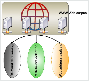
the proactive strategy is being conducted to analyze the impact of maleficent elements on websites hosted on the dark web. All such websites have been tested from different locations while keeping in mind that these websites were not in normal status and therefore, the alternate workstations were used in order to avoid any unusual situation as illustrated in Figure 1. During testing period, the multiple vulnerabilities were identified in various categories such as Adults, Drugs etc. Around 650 websites were tested from www web corpus and more than 60% of websites found to be vulnerable and unprotected from various attacks. During this operation, the different activities were performed in order to get the desired outcome which eventually turned the activities into a proactive strategy.

Figure 1: Proactive research methodology.
Lupinepublishers-openaccess-robotics-mechanical-engineering-journal

Relevant data mining

During the operation of dark web data mining, some indexing related uncouth situation was occurred because the addresses of the dark web do not appear in normal format. Further, web address belongs to dark web are exceptionally complicated and employs a more robust and modern encryption algorithm. It is much hard to recall the web address belongings to the dark websites due to URL length as 56 bytes long. These features make mining challenging; therefore, for a proactive strategy a script was designed that mines the URL by visiting multiple search engines based on user input and creating a unique result set. In addition, live activities were performed to catchup all those domains that having chances of becoming inactive because for security reasons, onion sites may become inaccessible after some time. Another script was designed to forecast the status of onion domain active or not, and also it reverts the status code (200,301,404,403 etc.), the title of the web page and saves results if the domain can redirect to some other domain [22]. Further, it is crucial identifying the gap for dark web hosting and every aspect is needed to investigate the areas which were ignored. Spiders/ crawls can use different techniques, such as brute force, to discover vital files or configuration files that have been missed or concealed. A SOCKS proxy is used to establish connections to the hidden services by the crawlers, which are written in Python. The crawler receives the first onion domains or seeds from the surface web’s publicly available directory. A separate file is created for each seed that is scraped and the new links that are discovered. The new links were crawled again to find other new links. The scraping of new link is performed two more times until no new connections can be identified. The crawler did not scrape hidden services that required user authentication or were behind subscription pay-walls. Getting the user information such as email address, phone address, how generally the users act, details about the admin, all are required and therefore, information gathering also includes looking into exposed tokens, API endpoints, API entry points, and reading the parameters. The API is used to find login information in files; client-side validation is available, although it is preferable. Having as much knowledge about the target as possible makes work more accessible and manageable. Therefore, all potential hostnames connected to target and relevant open ports have been considered. The domain-level structure of the dark web has been examined, and all sub-domains of a certain domain are aggregated under it and indicated as a single individual node of a graph. The onion possessing two sub-domains en.ABC.onion and my.IMS.onion [23], each of these sub-domains and their internal web pages are considered as a single node of graph identifiable by respected domain name. As a result, each edge in the graph connecting nodes A and B symbolizes a hyperlink inside domain A’s web page referring to a web page included in domain B.

Maleficent detection

The web maleficent detection is a complicated process of identifying vulnerabilities in web traffic; the loopholes are a significant cause of data breaches, hacking, and ransomware, among other things. The information gathered was utilized to start the maleficent detection of the web hosts Two techniques are used for this detection i.e., manual testing and automated testing. As a result of the manual testing being conducted by humans, it is essential that the testers think like a hacker. The tester examined each component of the target by hand and used a variety of methods based on his expertise of how to defend it. Automated testing makes use of scripts, tools, and software to replicate the same process by repeating defined tasks. It is handy when viewing source code since it detects weaknesses and unexpected vulnerabilities immediately. In automation testing, software such as ZAP, Burp Suite, and others are utilized [24].

Web address analysis

It has been determined that web addresses have a life expectancy, which is a novel classification. The concept of the invoked web address lifespan has been added, which quantifies the duration between the first and last occurrences of a web address in a data collection. It is related to the dynamics of content interest on the dark web. This notion is applicable to a variety of hosting considerations, as well as online cache activities. A simple parametric function closely linked to the probability density function well approximates the distribution of invoked lives. A unexpected finding was made using this model: the anticipated lifespan of a web address is asymptotically equal to the time frame of observation. It’s also surprising to see a classic and well-behaved web family of statistical distributions at all [25]. This is particularly noteworthy since a substantial volume of web addresses in online traffic are nonces inside the scope of web data corpus. Furthermore, the structure inherent in web addresses was evaluated by comparing the use of path hierarchy vs query string on a range of dark sites. Surprisingly, static material is supplied via a path-depth structure, whereas query parameters include personalized content. Despite the fact that the two morphologies are functionally similar, there is a path-depth versus query-parameter dichotomy. Also, a web address does not have to represent the content of the resource if it is not used for search and resource discovery or is handled in another way. As a result of the widespread usage of query strings in many applications, the web address is no longer viewed as a simple node in a hierarchical file system [26].

Dark Web Data Selection Strategy

While exploring the dark web for data collection, it was much hard to find the appropriate data as most of the time accessibility issue hurdles reaching to specific hosted data. An obscure part of the Internet that can only be accessed with special software is known as the dark web Although there are several dark web technologies, they all have the feature of employing encryption [27], to provide anonymity.

Dark web alive time

When it comes to selling illegal items and services, most dark web sites, also known as dark markets, are similar in functionality and structure to other well-known websites. They provide a wide range of illegal commodities and appear to cater to customers seeking specific content. As a result, one cannot be certain if the dark web will be accessible online or not because web addresses for such websites are not available throughout the session.

Maleficent detection is a time-consuming process that might take anything from many hours to several days to finish [28]. There is no guarantee that a website will be available during the maleficent assessment task. In the same way as ordinary websites, dark websites are linked to one other and to each other. When webpages did not have hyperlinks, users had to know the precise URL to find them. Thus, hyperlinks serve as the foundation for how users navigate this network, connect to domains, discover information, and interact with other users. Using social network analysis, these linkages may be examined, revealing the web’s connections [29]. In the dark network, websites with more inbound and outbound hyperlinks may be regarded more popular and significant for the dissemination of information inside the dark network, Network analysis may assist in determining not just how information is transmitted and exchanged within network structures, but also the significance of certain websites to the network. A tiny dense cluster [30], of nodes, similar to other Internet topologies, may constitute the network’s hub and direct the flow of information. Significant ramifications for how communities grow and operate might result from this, as could the tactics employed by law enforcement authorities to discover and remove unlawful users and material. Similarly, considering the web address delay response, the time it takes the web application server to complete one request is referred to as latency. Congestion has crept into the dark network [31], and the flow management system has failed to keep up with it. The issue of high latency is not the only one that has to be solved. Furthermore, the dark network is quite variable. Because queries are routed via several computers across the world, the dark network will never be as fast as the surface web. As a result, network latency will always be a problem. It took a long time to examine the endpoints and other features of websites since there were numerous instances of web address delay. An excessive amount of HTTP requests was made to the web-based application server because of this high delay rate. Further, checking some static web sites on dark web environment, Many CMS-based websites [32], are challenging to evaluate since the community is always working on security fixes and looking for new vulnerabilities. It has also been discovered that several hidden websites have not been updated.

Comparative Scenarios

In order to examine the roots of the dark web hosting script, the comparative scenarios are developed which enhanced the chances of getting accurate data and presages upcoming attacks.

(i). Similar attributes: The principles of running a web environment are the same on the surface and dark webs because Onion services are the part of the dark web, it does not expose the host’s IP address but on the surface web, the IP address is accessible to everyone, therefore a misconfiguration can reveal the server’s IP address [33]. When comparing the characteristics of the surface and dark webs, the dark web was found to be misconfigured. Exploiting a dark web site, as in the surface web, might disclose dark web users who visit the dark web site. As a result, identifying a surface web site relevant to a dark web site based on ownership and developer can increase the odds of understanding the user’s activity. The Fisher’s Exact Test (FET) [34], was used to assess the connections between surface and dark websites. The FET confirms the strong correlation between the web environment and maleficent. Unlike the dark web (1%) where this occurrence is rare, the surface web (12.2%) is more likely to experience the maleficent than the dark web (1.3%) shown in Table 1. It was discovered through a more detailed study that this relationship is only significant in paste locations. As a result of this, attackers on the dark web may be stealthier and try to avoid detection by not changing passwords on their accounts, indicating a certain degree of skill. The observed variations in the underground forums are insignificant.

Read More About Lupine Publishers Journal of Robotics & Mechanical Engineering Please Click on Below Link: https://robotics-engineering-lupine-journal.blogspot.com/

Wednesday, 22 March 2023

Lupine Publishers| Development of Novel Composite Biomaterials for Use as Biodegradable Adsorbents and or Bio-Carriers During Wastewater Treatments Using Galerkin’s Finite Element Analysis

  Lupine Publishers| Journal of Robotics & Mechanical Engineering


Abstract

In this study, the development of novel composite biomaterials for use as biodegradable adsorbents and or bio-carriers during wastewater treatments was carried out using Galerkin’s finite element analysis. Several literatures in the past showed that the increment in number of wastewater treatment plants, made it difficult to manage the wastewater systems. Therefore, to ensure proper discharge from the wastewater treatment plants, new and stricter regulations for nutrient removal have to be incorporated. Several wastewater treatment measures that have been adapted to date includes: bio filtration, ion exchange, sedimentation, solvent extraction, chemical oxidation, membrane processes, coagulation, oxidation, Fenton process, and electro coagulation. The data used in this analysis were obtained from various literature sources and were analyzed using Galerkin’s finite element analysis method in order to develop models that would analyze the empirical parameters affecting wastewater treatments. The result obtained showed that the removal efficiencies for wet season are TDS (16), BOD (63), COD (55.8) and N (72%) respectively. The results justified the presence of high impurities as a result of influx of wastes from industries, households etc into the river body.

Introduction

Freshwater is the chief constituent of the planet and is essential for the survival of all living organisms [1-5]. The continuous addition of undesirable chemicals, agricultural wastes [11], civilization, industrial wastes, other environmental and global changes etc. reduced the quality of water resources [18]. Over the last century, major part of the world has been facing degradation of environment because of the continuous growth in population [12]. With the growing population, there is a striking increase in usage and wastage of water for domestic purposes. Domestic wastewater is usually the water discharged from household purposes such as toilets, dishwashers, showers, sinks, washing machines etc. [8]. The contamination due to organic pollutants is very dangerous due to their various side effects and carcinogenic nature. Several literatures reveal some methods for the removal of organic pollutants from water. The methods used in literature suggested that the methods might depend on their physical, chemical, electrical, thermal and biological properties [13-17].

While other researchers proposed that oxidation, reverse osmosis, ion exchange, electro-dialysis, electrolysis, adsorption as another method of wastewater removal etc. Of course, reverse osmosis, ion exchange, electro-dialysis, electrolysis and adsorption are excellent wastewater removal technologies. Several reviews were made in the past in order to determine the best wastewater removal technique. Others argued that before talking about wastewater removal technique, that it is imperative to firstly divide the wastewater treatment procedures into primary and secondary treatment processes depending on either the removal of solid particles physically by using screens or biological treatment where microorganisms consume organic matter and convert it into inorganic compounds. [6-7] Nitrogen and phosphorus removal are the major goals of wastewater treatment which can be carried out biologically in an economically feasible and environmentally friendly manner in recent years [19]. In case of phosphorus, sometimes biological methods are not efficient because of lack of carbon. Hence, to make up for the lack of carbon, some additional organic matter is added to the biological reactors which increases the cost of operation and results in generation of one more pollutant. However, there is an alternative for this problem which is the use of enhanced biological phosphorus removal which works efficiently for domestic waters with Low C/N ratio [1]. Nowadays, with the increment in number of wastewater treatment plants, it has become challenging to manage the wastewater systems. Therefore, to ensure proper discharge from the wastewater treatment plants, new and stricter regulations for nutrient removal have been incorporated. Several wastewater treatment measures that have been adapted to date include bio filtration, ion exchange, sedimentation, solvent extraction, chemical oxidation, membrane processes, coagulation, oxidation, Fenton process, and electro coagulation [1,2].

Adsorption is today regarded as the best water treatment procedure because of its universal nature, ease of operation and inexpensiveness.it has a removal capacity rate of 99.9% .The adsorption has some limits which made its removal rates not to perfect [9-20]. To comply with these limits, there is a need for modeling and operation control of wastewater treatment plants. However, the modeling of wastewater treatment systems tends to become intricate due to certain characteristics such as unusually long residence times, plenty of tunable kinetic parameters and large variations in influent component flow rates. Nevertheless, with the advancements in technology, activated sludge modeling, flow sheet simulators and computational fluid dynamics have emerged as some significant tools for modeling Wastewater treatment plants. Over the years, dynamic modeling has come across as a remarkable approach for developing operational models in process design and management. Moreover, these Models help in establishing operating policies and control strategies for the wastewater treatment plants which in turn maximizes the plant performance and comply with the required permit limits. The mathematical modeling of wastewater, the performance of the pH, dissolved oxygen demands, and other wastewater analytical parameters were not captured in literature

Mathematical Formulation:

The mathematical formulation can be carried out by considering the following assumptions

1. The evolution of the biological oxygen demand and the dissolved oxygen for freshwater treatment are governed by partial differential equations

2. The outfalls are located at points

3. The convex functions are known

4. The fluid medium is continuous.

5. The soil matrix is continuous.

6. The fluid is in mot ion.

7. The soil medium undergoes consolidation.

8. The fluid is incompressible.

9. The air phase is continuous and is at atmospheric pressure.

10. Flow is laminar and Darcy’s law is valid.

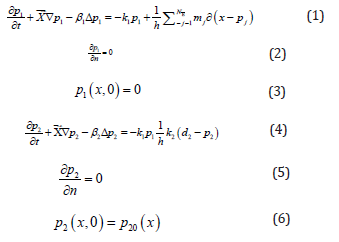
The biological oxygen demand and dissolved oxygen concentrations in a point u and a time t be denoted by ρ1(u,t) and ρ2(u,t) respectively .The boundary equations can be obtained by

Considering the following boundary value problems

Let h(u,t) and x ⃗(u,t) be the height and the mean horizontal velocity of the fluid layer obtained as a solution of saint venant equation. ∂(x-p_J) is the dirac measure for point p_i and the parameters β1> 0, β2 >0 represents the horizontal viscosity coefficients involving the dispersion and turbulence effects. Parameters k1> 0, k2 >0 represents the kinetic coefficients related to temperature and transference of oxygen through the surface and ds is the oxygen saturation density which can be drawn from experimental measurements.

Read More About Lupine Publishers Journal of Robotics & Mechanical Engineering Please Click on Below Link: https://robotics-engineering-lupine-journal.blogspot.com/


Tuesday, 7 February 2023

Lupine Publishers| Design of A Servo-Articulated 4-Degree-of-Freedom Tail for the Flying Control of A Bio-Mimicking Eagle Bird Robot

 Lupine Publishers| Journal of Robotics & Mechanical Engineering


Abstract

This paper describes the design principles and manufacturing techniques behind the construction of a life-size 4 degree- offreedom robot bird tail that mimics the pygostyle articulation of a 2.4-meter wingspan eagle bird. The tail provides for elevatorpitch and rudder-yaw control as well as a significant degree of lift that supplements the lift from the main wing. The tail is an articulated feather-like design that is modelled on the pygostyle of a real eagle bird. The design was based on (i) research into bird anatomy from avian anatomy books and (ii) studying slow-motion eagle flight manoeuvres from YouTube video clips. Future work concerns experimental work into validating the mechanics and aerodynamics of its design together with reduction of its weight.

Keywords: Biomimicking Eagle Bird Tail; Feather-Skeletal Accurate Bird Tail; Morphing Robot Bird Tail; Robot Bird Yaw-Pitch Control; Robot Bird Tail Manufacturing Process; Robot Feather Fanning Mechanism; Robot Pygostyle

Background to the Tail

This paper describes the tail design principles of a bird robot that forms one component of a longer-term plan to build a 2.4-meter wingspan biomimicking eagle bird robot that can fly similar to an eagle. The design principles are described in limited detail due to the page constraints of this paper. The robot is considered a “big bird” robot as distinct from robots that emulate insects or hummingbirds. This eagle bird robot will be able to fly and hover by flapping its wings. Flapping flying robots are not new since such robots, known as ornithopters, have been in existence for more than a hundred years together with, recently in the last few years, much improved ornithopters such as the ingenious Festo Smart Bird, [1]. However, these big bird ornithopter robots cannot hover and neither can they morph their wings from flying mode into a closed compact body shape format and vice versa. What is new about the robot and, in particular, the tail system described in this paper is that it is designed to mimic accurately the feather and skeleton system of an eagle bird such that it can hover as well as close its main wings and tail into a compact shape. As such the robot will have 12 feathers in its tail and 24 feathers in each of its two main wings thus the robot will possess a total of 60 feathers. Furthermore, its main wings will have wrist bending and forearm rotation joints. The main wing up-down flapping articulation mechanical power pectoralis major and supracoracoideus biomimicking muscles will come from two pairs of ultra-low impedance muscle actuators that are work-inprogress. The 12-feathered tail, which is the subject of this paper, is able to, (i) open and close its feathers in a fanning motion, (ii) rotate the pygostyle about an athwartships axis to give flight pitch control, (iii) rotate the pygostyle about a longitudinal axis to give yaw control that is in conjunction with pitch control and, (iv) shift the feathers left and right to give some control of flight balance about the longitudinal axis in conjunction with the pitch and yaw control.

Robot Tail Overview

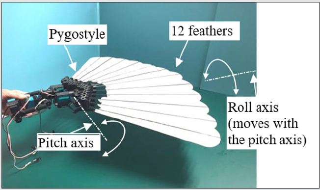
The design of the tail is largely based on (i) YouTube slow motion video clips of eagles, e.g. [2], and (ii) avian anatomy and physiology described in an illustrated book, entitled, “Manual of Ornithology: Avian Structure and Function” by Proctor & Lynch, [3]. In anatomical terminology, tail feathers are called retrices (singular: retrix) and are mounted on the pygostyle and, in turn, the pygostyle is mounted on the jointed caudal vertebrae, that is at the end of the backbone. The pygostyle, via the muscle-actuated caudal vertebrae is given up-and-down, side-to-side, and twisting motion. The feathers are given opening and closing motion by muscles mounted on the pygostyle. The robot tail design, shown in a photograph, Figure 1 and schematically, Figure 2, is designed to emulate almost all of the motions of a real bird tail.

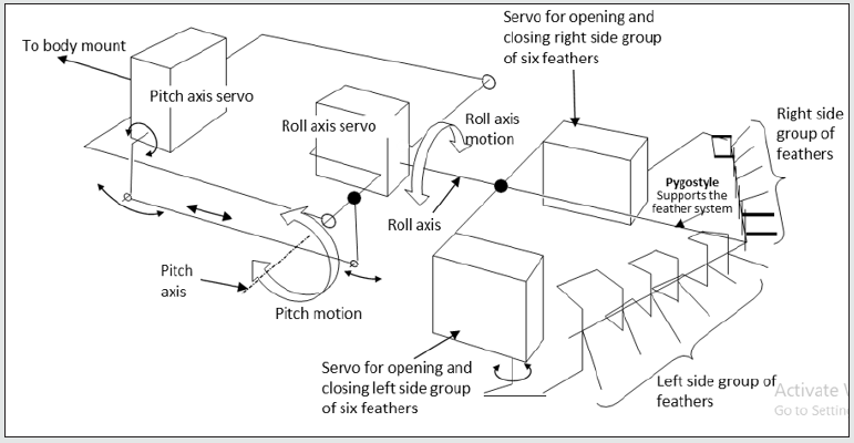
The tail, [Figure 2], is actuated by four Futaba BLS152 servos that control its joints to give (i) pitch control (quantity 1 servo), (ii) roll control (quantity 1 servo), (iii) independent left-side group of six feathers control of opening and closing, (quantity 1 servo) and (iv) independent right-side group of six feathers control of opening and closing (quantity 1 servo).

Figure 1: Photograph of the robot eagle bird tail. It consists of (i) 12 feathers, (ii) a pygostyle that holds and articulates the feathers to open and close, (iii) an articulated servo-driven pitch axis that drives the pygostyle up and down and, (iv) an articulated servo-driven roll axis that rotates the pygostyle.

Lupinepublishers-openaccess-robotics-mechanical-engineering-journal

Figure 2: Schematic diagram of tail actuation system and pygostyle showing pitch and roll axes plus left and right side feather group servo actuated systems.

Lupinepublishers-openaccess-robotics-mechanical-engineering-journal

Feather Opening and Closing Action

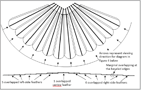
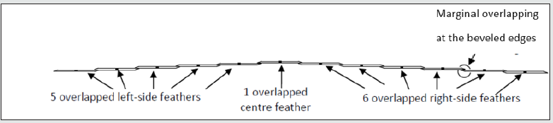
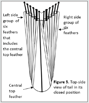
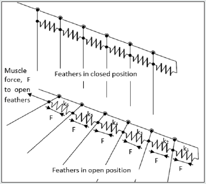
Figure 3 shows a top view of the tail in its open position and Figure 4 shows a view along the axes of each feather viewed from the rear. It can be seen from Figure 4 how the feathers marginally overlap to give a wind proof surface. There are 12 feathers that make up the tail. Six of these feathers make up the left side group and one of these six is the central feather that is the topmost feather of all the 12 feathers. The remaining six feathers form the right-side group. Note, importantly, that all flying feathers on a bird move to a lower position as the feathers move away from the centerline of the body. As an approximation, the tail in its closed position, the outermost left and right feathers extend outwards from the center by 60° when they open. Similarly, the 2nd pair of feathers, working in from the outermost pair, extend by 50°, the 3rd pair by 40°, the 4th pair by 30°, the 5th pair by 20° and the remaining innermost pair by 10°. This is an approximation because the feathers are directed slightly towards the center in the closed position, so the feathers actually extend more than 60° for the outermost pair and likewise more than 10° for the innermost pair. However, the approximation gives the reader an idea of how adjacent feathers must angularly interact in order to produce the correct fanning action when opening and closing. For example, we will assume that the outermost feather is driven by a servo. The servo will extend this outmost feather by 60° from the closed position to the open position. We will call the outermost feather, feather 1; the next inner feather, feather 2 and so on. Feather 1 should extend feather 2 by 50° and feather 2 should extend feather 3 by 40° and so on. Thus, there needs to be a discrete angular mechanical gear ratio between each feather working from feather 1 to feather 6 as follows; 6:5, 5:4, 4:3, 3:2, and finally 2:1. Figure 6 shows how this interactive set of gear ratios could be achieved using an interconnected serial spring system that could be physically enabled by biological tendons. This is probably the mechanism for a biological bird.

Figure 3: 12-feathered tail in open-tail position.

Lupinepublishers-openaccess-robotics-mechanical-engineering-journal

Figure 4: Rear view of all 12 tail feathers in open–tail position viewed from the rear in an arc in directions as shown above in figure 3. Note that the feathers overlap marginally at their edges by 1cm that matches the beveled edges.

Lupinepublishers-openaccess-robotics-mechanical-engineering-journal

Figure 5: shows a top view of the tail feathers in their closed position.

Lupinepublishers-openaccess-robotics-mechanical-engineering-journal

Figure 6: Method for obtaining correct fanning angle ratios. Tensile forces in equilibrium. Thus, arrange spring stiffnesses, k1, k2, k3, k4, k5 and k6 to give required deflection in order to required feather angle change during fanning.

Lupinepublishers-openaccess-robotics-mechanical-engineering-journal

Design and Theory of the Pygostyle Opening and Closing Mechanism

Figure 7, photographs (a) and (b), show top- side and underside views respectively of the pygostyle opening and closing articulating mechanism with the feathers in the open position. Conversely, Figure 8, photographs (a) and (b), show the feathers in the closed position.

The kinematic theory behind the serial articulating link mechanism is illustrated in Figure 9 which shows two adjacent feathers, feather 1 and feather 2, with rotating joints located at a1 and a2 respectively. Feather 1 is considered the driver feather and feather 2 is considered the driven feather. The reason for this arrangement is that feather 1 is further out from the center of the robot and the outermost feather is driven by one of the pygostyle servos. A feather that is further out drives the next inner feather through a smaller fanning angle than its own, 60° to 50° or 50° to 40° and it is always good practice for an actuator to drive a reduction ratio rather than vice versa because the inertia seen by the actuator is reduced and the actuator displacement is increased thus greater control precision is achieved. The distance a1a2 is set by the feather pitch and is equal to 18mm. Suppose that the required reduction ratio between feather 1 and feather 2 is 0.421. Meaning that feather 1 is the driver and moves by 10° and thus feather 2, the driven, is required to move by 4.21° in order to give an effective fanning operation. We now set the lengths of links a1c1 and a2c2 to be 7.89mm and 18.74mm respectively, thus 7.89/18.74 = 0.421. Both feathers are now temporarily fixed in their mid-range positions, a1b1 and a2b2. Two links are generated for each feather, a1c1 and a2c2 and these links are of lengths 7.89mm and 18.74mm respectively as calculated just previously. These links are then set mutually parallel and a link, c1c2, generated between them where the link is of such a length that angles a1c1c2 and a2c2c1 are both 90°. The length of c1c2 is calculated as 14.36mm. The links a1c1 and a1b1 are now welded together at a1 and likewise the links a2c2 and a2b2 are now welded together at a2. Feathers 1 and 2 may now be released from their temporarily fixed positions and the mechanism is now serviceable over a limited angle range either side of the mid-range position meaning that it will give good linearity and an accurate gear ratio for a limited range of angles. Figure 10 shows relationship between feather 1 and feather 2 angles over +/-30° angle change of feather 1. Figure 1 shows that the error of the link mechanism stays less than 5% over a range of 60° range of the input driver crank angle. Such an error is considered acceptable and is seen as accurate because the feathers remain marginally overlapped without any gap appearing. Figure 11 The link geometry has been worked out for each feather-to-feather connection. A problem that occurs is in implementing the link mechanism such that it is highly compact. This took many hours to calculate and design with many iterations.

Read More About Lupine Publishers Journal of Robotics & Mechanical Engineering Please Click on Below Link: https://robotics-engineering-lupine-journal.blogspot.com/
Monday, 2 January 2023

Lupine Publishers| A mini review on Magnetic Lead Screw Technologies

 Lupine Publishers| Journal of Robotics & Mechanical Engineering


Abstract

Magnetic lead screw (MLS) is the upcoming alternative technology to conventional lead screw technology in modern engineering. MLSs use the principle of magnetic levitation for achieving the linear motion of the nut by converting the rotary motion of the screw. The advantage of magnetic levitation in the MLSs eliminates the contact between the screw and the nut by resulting in zero contact force, longer life with less operational maintenance and costs. This review presents the advancements in the Magnetic lead screw technologies which elaborate the design parameters, manufacturing procedures, and areas of applications of the MLS.

Introduction

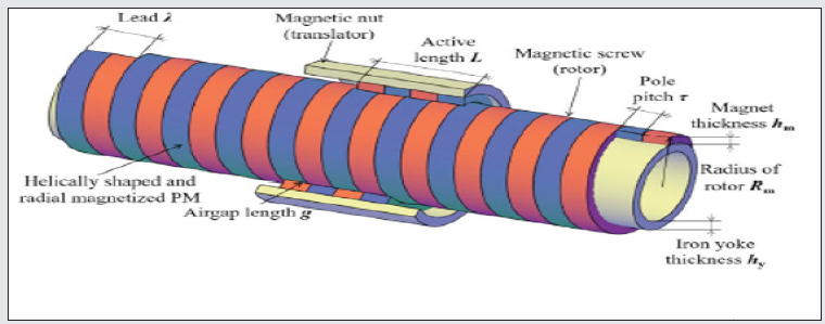
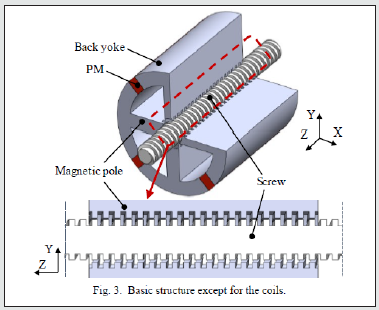
Lead screw has a wide range of applications in the industrial sector ranging from conventional lathe machines, servo motors to wave energy conversion systems. The recent advancements in the lead screw technology for converting the rotary motion to linear motion and vice versa include the development of contactless Magnetic Lead Screw (MLS) technology. The construction of MLS consists of several helically cut permanent magnets (PMs) attached to the outer surface of the screw and the inner surface of the nut. The working principle utilizes the magnetic levitation in between the screw and the nut, such that due to the helical cut of the PMs the rotating motion of the screw results in achieving the lead for the nut as shown in Figure 1. The performance of the screw depends on various design parameters, methodologies, and the alignment of the magnetic field which causes the translatory motion for the nut (moving body).

Figure 1: Structure of Magnetic Lead Screw (MLS) [1].

Lupinepublishers-openaccess-Surgery-Casestudies

Design Parameters

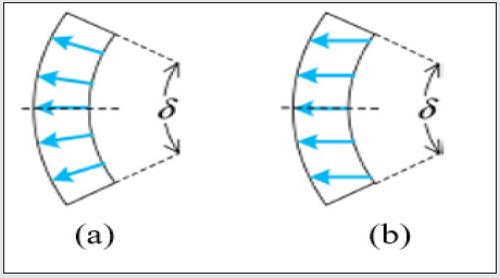
The design parameters which influence the performance rate of the MLS are the Rotor Radius, Translatory Radius, Permanent Magnet Width [1], Permanent Magnet Thickness, Air Gap, Force Density, and Pole Pitch (Pitch between two adjacent poles) [2]. The parameter force density defines the ratio between the thrust force on the screw to the total volume of the MLSs permanent magnets and the Rotor radius. It is a significant parameter that affects the air gap between the screw and the nut to maintain optimal magnetic flux for achieving the linear motion. Zhu et.al [3] mentioned a significant increase in thrust force and a decrease in force density which is observed with a change in rotor radius. The thrust force increases with an increase in magnetic thickness and width. Gao et.al showed the the usage of parallelly magnetized permanent magnets results in distortion of air-gap flux density and decrease in average thrust force and torque values, whereas the radially magnetized permanent magnets resulted in smooth air gap flux density and thrust forces [4]. The difference between the parallelly magnetized and radially magnetized magnetic fields is shown in Figure 2.

Figure 2: (a) Radially Magnetized PM (b) Parallelly Magnetized PM [4].

Lupinepublishers-openaccess-Surgery-Casestudies

Few More Designs

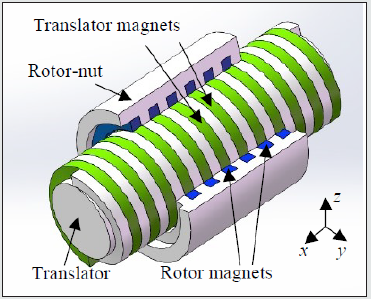
Few more designs are shown in Figure 3 where a single helix magnetic lead screw system [5] is proposed for a wave energy converting system and a magnetically levitated lead screw system [6] is proposed to eliminate the number of magnets by using a coil in between the two adjacent magnets.

Figure 3: (a) Single Helix MLS.

Lupinepublishers-openaccess-robotics-mechanical-engineering-journal

Figure 3: (b) Magnetically Levitated Lead Screw System (MLLS) [5] [6].

Lupinepublishers-openaccess-robotics-mechanical-engineering-journal

Conclusion

This review reports the advancements in the Magnetic lead screw technologies by highlighting the design parameters, design methodologies of various types of Magnetic lead screw mechanisms. The Magnetic Lead Screw is more advantageous compared to Conventional lead screw mechanisms for its wide range of applications which utilizes a non-contact type of actuation.

Read More About Lupine Publishers Journal of Robotics & Mechanical Engineering Please Click on Below Link: https://robotics-engineering-lupine-journal.blogspot.com/

Wednesday, 16 November 2022

Lupine Publishers| Logical Failure Analysis Diagram by Persian Curve

 Lupine Publishers| Journal of Robotics & Mechanical Engineering


Abstract

Failure analysis diagram (FAD) is an important tool in safety assessment of cracked structural systems. Conventional methods for determination of (FAD) is expensive and contain epistemic uncertainty. Toward the remedy, failure is considered as change of state of the system. Based on logical reasoning and concise mathematics a method, called the change of state philosophy is developed and used for analysis of change, and is shown to be a unified tool for development of (FAD). The work is verified via concise logical reasoning and comparison of the results with those of the others.

Keywords: Failure Analysis Diagram;Logical Failure Analysis;Persian Curve;State Functions;Phenomenon Functions

Introduction

A conventional tool for assessing the integrity of structures containing cracks is, fracture mechanics and the failure assessment diagram (FAD) [1-18]. The (FAD) is a combination of the limiting conditions for load, the crack size and fracture toughness or yielding stress. The abscissa is the load ratio and the ordinate is the toughness ratio. The toughness ratio is defined as a function of the load ratio. Classical fracture mechanics contains epistemic uncertainty and is unreliable. As a result, the conventional (FAD) is also unreliable. Change of state philosophy (CSP), which is digested in the Persian curve (PC) is developed as a remedy for removal of uncertainty as follows.

Mathematical Basis

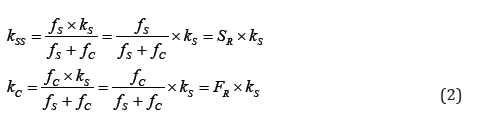
The failure phenomenon is conceived as a change in the state of the system [19-39]. A decreasing parameter (capacity, toughness and etc.) of the system is called stiffness. The inverse of stiffness is called flexibility. The (CSP) formulation is commenced by the obvious Eq. (1) as shown in Figure1, in which (kSS=kS-kC) is the system stiffness at changed state, (kS) is the system stiffness at intact state, (kC) is the change stiffness, (fSS=fS+fC) is the system flexibility at the change state, (fS) is the system flexibility at change state and (fC) is the change flexibility.

Equation (1) is rearranged to obtain the (kSS) and (kC), in Eq. (2):

In which the phenomenon functions (collection of the failure function (FR) and the survive function (SR)) are defined in Eq. (3):

Since obvious concepts are used, then the proposed method is free of epistemic uncertainty. The unknown parameters (kC&fC) should be explicitly determined. The investigation for explicit definition of the aforementioned functions, is continued in the next paragraph via definition and construction of the so called, state functions.Consider (ks = fs= 1) and insert into Eq. (3) to define the destination function (D) and the origin function (O), which are collectively called the state functions and the state ratio (R) in Eq. (4).

Figure 1: Persian curve basic equations.

Lupinepublishers-openaccess-Surgery-Casestudies

The state functions may be considered as solution of the boundary value problems in Eq. (5), in which (min) and (max) denote minimum and maximum respectively:

The (R) with one end in the infinity, is not a good working parameter. Therefore, the state variable (ξ ∈[0,1]) with a zero value (ξ = 0) at the origin and a unit value (ξ =1) at the destination is defined. The state variable is the phenomenon’s abstract lifetime. In terms of the state variable, the boundary value problems in Eq. (5) are rewritten in Eq. (6):

The authors used their experience in structural mechanics, finite element method, mathematics and extensive research [37] to solve Eq. (6). The results is the state functions defined in Eq. (7):

Via definition of the (kSS) and the (fSS) and the concept of crack compliance (fC) in fracture mechanics [4], the authors detected a fact that, the (fC) is directly proportional to the (kS)! This detection is called “the Persian Principle of Change (PPC)”. In view of this principle the (fC) is defined in Eq. (8):

Insertion of Eq. (8) into Eq. (3) concluded in the general definition for the phenomenon functions in Eq. (9):

Toward better definition and preparation for using reliable data, Eq. (9) is rewritten in Eq. (10) in terms of the positive control parameters (aM) and (b) [37].

To this end the proposed formulation is mathematically in abstract form. Consequently, it is a certain universal formulation, in a sense that it is independent of geometry, coordinates, material properties, size and changing agent. Therefore, it equally applies to all natural-phenomena.

Persian Curve

The proposed formulation is derived based on logical reasoning and concise mathematics, consequently, it is reliable and free of epistemic uncertainty. To prepare for determination of control parameters for a phenomenon, the (FR) is renamed as Persian-Fasacurve (PF), the (SR) is renamed as Persian-Shiraz-curve (PS) and the two collectively called the Persian curve (PC), defined in Eq. (11), in which (PO) is the ordinate of the origin point (O) and (PT) is the ordinate of the truncated (end) point (T).

In comply with the vocabulary of human knowledge, the (PS) is the unified equation for capacity and reliability representing a decreasing data and the (PF) is the unified equation for the probability and fragility representing an increasing data. Moreover, in comply with the common practice in stochastic analysis the (probability) density distribution, here called the Persian-Zahedancurve (PZ), and defined as the derivative of phenomenon functions with respect to the ( ξ ) and is casted in Eq. (12), in which (D(1)) is derivatives of (D) with respect to ( ξ ).

In order to determine the control parameters, Eq. (11) is rearranged as in Eq. (13):

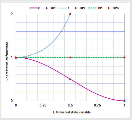
Eq. (13), in terms of control parameters (aM& b) is nonlinear. An artifice is used, to determine the control parameters (aM& b) from Eq. (14) in terms of the (KPS) ordinates, equally applies, to both of increasing and decreasing data as shown in Figure 2.

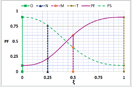
The Key Points (KPS) are defined as the Origin point (O), the Middle point (M), the end point (T) and the Next point (N) (a point between the other three), in Eq. (15) and shown in Figure 2 for both of decreasing and increasing data:

Figure 2: Key points on Persian curves.

Lupinepublishers-openaccess-Surgery-Casestudies

Unified Persian Curve

Intensive investigation of the reliable capacity data in the literature [37], concluded into the key points, on the lower bound of capacity, in Eq. (16).

O(0.0,1.0) N (0.25, 0.86) M (0.5, 0.4) T (1.0, 0.1) (16)

Insertion of Eq. (16) into Eq. (14) concluded into the control parameters, in Eq. (17).

Substitution of control parameters in Eq. (17) into Eq. (11) and Eq. (12) concluded in the unified capacity function (PSU), unified fragility function (PFU) and unified density function (PZU), in Eq. (18).

Failure Assessment Diagram

Persian curve is defined in terms of an abstract life time called state variable in a unit interval (ξ ∈[0,1]) . In real phenomena, the lifetime (λ ) is selected in a truncated interval ( [ , ]) o T λ ∈ λ λ , where ( O λ ) is the lifetime origin and ( T λ ) is the lifetime destination. Lifetime is a characteristic of the system. In common practice the ratio (to make it user friendly) of a predefined parameter (FY) and an intentionally defined one (FE) is expressed as lifetime (λ ), as in Eq. (19).

For the case of structural systems (FY) is the yield stress, (FE) is the Euler’s stress and lifetime (λ ) is the relative slenderness ratio, as in Eq. (20). The other parameters are (Le) effective length, (r) is radius of gyration, (E) is initial modulus.

For systems containing flaw the lifetime (λ ) is denoted by (Lr). In order to use the Persian Curve, the lifetime (λ ) should be mapped on the state variable (ξ ), as in Eq. (21).

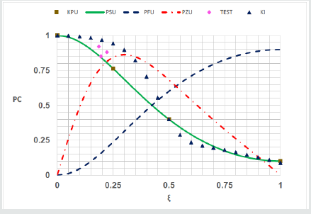
Figure 3: Compare PC with FAD (KI)

Lupinepublishers-openaccess-Surgery-Casestudies

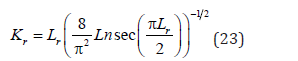
Example 2: Compare the Unified Persian curve with the FAD defined in Eq. (23).

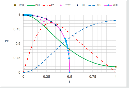
Solution: The FAD from Eq. (23) (KIII) [6, 9, 12, 18] is compared with the unified Persian curve (PSU) in Figure 4. The lifetime is mapped onto the state variable as ( 2.25 ) r L = ξ . A set of test data (TEST) [40] is also shown. The (KIII) goes through the unified key points, but the test results located under it, that is contain uncertainty and is not reliable. In order to show the power of the work in fitting curve on data, the function in Eq. (24) (KIIIR) is also shown in Figure 4.

Figure 4: Compare PC with FAD (KIII & KIIIR)

Lupinepublishers-openaccess-Surgery-Casestudies

These figures shown that although all of the conventional (FAD)s go through some of the key points, but overestimate the test results, then contain epistemic uncertainty. The validity of the (PC) as logical (FAD) is verified.

Discussion

The conventional (FAD) is based on conventional fracture mechanics, which is based on singularity of stress at crack tip. Stress singularity at crack tip is a wrong concept, then the conventional fracture mechanics and the (FAD) contain epistemic uncertainty and are not logical. On the other hand, the proposed formulation is logical and reliable. The parameter (Lr) is defined as the ratio of the applied stress over the yield stress. Experience in determination of ultimate strength of structures shown that the combination of the material and geometric properties, in the form of the relative slenderness ratio (λ ), as in Eq. (20), is the necessary and sufficient condition. Note that, Eq. (20) is the inverse of the current definition of (Lr) when applied stress is selected as the Euler’s stress. Consequently, replacement of the (Lr) with the (λ ) is recommended. The (PC) used as (FAD) is necessary and sufficient for failure analysis of structures with cracks.

Conclusion

The following conclusion obtained from this study. The failure phenomenon is conceived as the change of state of the system. Based on logical reasoning and concise mathematics, the change of state is expressed in terms of the Persian curve. The Persian curve is completely calibrated from four key points on real world data. Making use of reliable data in the literature, the unified control parameters and the unified Persian curves are explicitly expressed in term of the state variable. The unified Persian-Shiraz curve (PSU) is proposed as a reliable (FAD). Validity of the (FAD) is verified via concise mathematical logics, and comparison of the results with those of the others. It is shown that the (PC) is sufficient for failure analysis of structures containing cracks.

Read More About Lupine Publishers Journal of Robotics & Mechanical Engineering Please Click on Below Link: https://robotics-engineering-lupine-journal.blogspot.com/
Monday, 26 September 2022

Lupine Publishers| Automated Chamber for Prickle Pear Cauterization

 Lupine Publishers| Journal of  Robotics & Mechanical Engineering


Abstract

Mexico is the world largest producer of cactus pear (Opuntia spp.) and is searching for new processes that allow to export them. The fruit is rich in nutrients but is highly perishable having ambient shelf life of 9 days. Cauterization and cryo-cauterization techniques have increased shelf life to 2 and 3 months without refrigeration. An automatic system was developed to flip the fruit towards the dry-ice wall inside a chamber. A horizontal actuator pushed the container to cauterize the fruit. The entire cauterizing process for each fruit lasted 23 seconds. By exchanging the dry-ice wall every 500 fruits, a 100% cauterizer efficiency was achieved.

Keywords: Automatic Chamber; Cauterization; Prickle Pear; embedded system

Introduction

Cactus pear (Opuntia spp.) is a fruit produced in arid and semi-arid regions around the world [1]. Mexico is the world’s largest producer of cactus pear (Opuntia spp.) with 79.4% of world production, and with 49,165 ha under cultivation [2]. Italy is now the world’s largest exporter of cactus pear to the European Union (EU), producing about 87 thousand tons annually in Sicily, which corresponds to 96% of the total Italian harvest [3]. Cactus pear is generally consumed fresh, but is highly perishable, showing high incidence of spots and rotting after 9 days. After 20 days at ambient conditions, almost 70% of the fruit was visibly damaged [4]. By cooling prickle pears to 10 °C, shelf life increased to 6 weeks [5]. Fresh cactus pear shelf life can be increased to 32 days in modified atmosphere packaging with less than 20 kPa CO2 [6]. A cauterizer cut and seal 120 pieces of fruit per hour [7]; cuts were made close to the cactus cladode at 150 °C during harvest, destroying thorns. After 2 months of storage, 78% of the pears were unspoiled. The application of uniform heat treatments has been effective in controlling postharvest diseases, but can damage the treated fruit tissue if not applied carefully. Excessive heating period may damage the fruit, while insufficient heating may leave non-sterilized surface segments [8]. Further developments of cauterizer machines by Hahn [9-12] applied heat to sliced pears. After applying a constant pressure of 100 kPa at 200 °C during 30 s to harvested cactus pears increased shelf life to 2 months, controlling effectively postharvest diseases [9]. However, heat application is expensive when many fruits are cauterized. A cryo-cauterization process used a pneumatic robotic gripper to press a cactus pear against a dry-ice wall within a thermally isolated chamber. Fruit cryocauterizing at 150kPa for 15s increased shelf life to 90 days, keeping 86% of marketable fruit [11].
Automation of agriculture tasks have improved pre-harvest, harvest and post-harvest stages. Machine vision sorting of fruits presents advantages of high accuracy, precision and processing speed [13]. Non-contact detection makes grading and sorting free of mankind diseases. Fruits and vegetables produced in farms are sorted according to quality and maturity levels and decisions taken of the market it can be sent on the basis of transportation delay [14]. Post-harvesting operations require quality detection [15] and skin defects [16]. A pepper robotic harvester system [17] avoiding stem and fruit damage would be highly successful. Although food processing methods extend the shelf life of fruit and vegetable products, fresh-cut produce may lead to flavor loss, discoloration, rapid softening, and increased rate of vitamin loss [18]. Emerging smart packaging reduce losses, maintain quality, add value and extend shelf-life of agricultural produce [19]. It alerts the consumer from contamination of pathogens, pesticide residues or food degradation in food packaging products [20]. Intelligent packaging with nano sensors senses and informs the condition of the product to provide information about quality during transport, distribution, and storage [21]. This technology may also be used to detect adverse reactions in consumers after taking food such as gluten, peanuts and tree nuts [22]. Automation for the application of these sensors is considered a future close innovation. In this paper, an automatic system used for prickle pear cryo cauterization within a very small chamber was developed. The chamber size obeys to the rapid melting of dry-ice caused by environmental conditions. A minimum number of operations is required and the system efficiency evaluated to cauterize 120 pears per hour.

Mechanism for Pear Cauterization

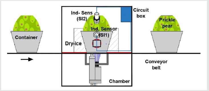
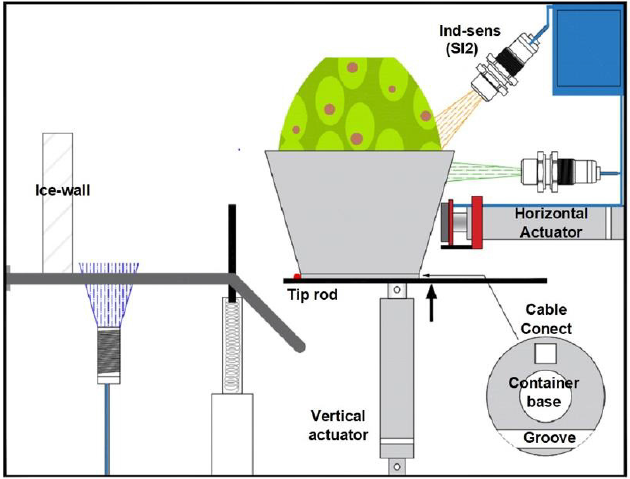
The top-surface sliced prickly pear is moved within a container into the cryo-cauterized chamber (Figure 1) by means of a conveyor belt. This band transports the fruits in a direction parallel to the dry-ice wall where cauterization takes place. A trapezoidal metal container resembles a porcelain coffee mug and holds the prickly pear (Figure 2) whose flat base stops at the bottom. The container base is 3mm thick (Figure 2) and has force sensor in between the base and the prickle pear. The system mechanism has to perform the following functions:

Figure 1: Prickle pear conveyor belt and cauterizer chamber.

Lupinepublishers-openaccess-Surgery-Casestudies

Figure 2: Bottom actuator and initial rotation operation.

Lupinepublishers-openaccess-Surgery-Casestudies

1. Detect when the prickle pear is present within the metal container.
2. Rotate it 9° counterclockwise.
3. Displace it against the dry ice wall.
4. Return it and deposit it to the original band.
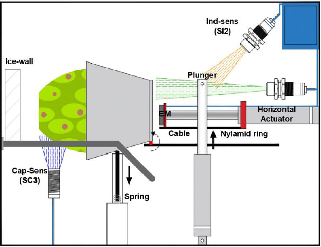
During the first stage, a conveyor belt transports the prickle pear to the cauterizer chamber rising the door in the left side. At the same time, it opens another door to exit the previous cauterized pear. For the second function, the mechanism used an actuator (A1) to flip the metal container (Figure 2). The linear piston or actuator (mod. LA 14, LINAK, Denmark) is characterized by its compact size being ideal for this chamber having a limited amount of space available. The aluminum actuator is used in harsh and cold environments up to -40 °C. A metal ring with a sectional groove is located at the container base (Figure 2). The lower piston plunger enters the groove and as it moves upwards, it turns the container base (Figure 3); a tip rod flips the container as the piston rises. After 45 or 50 degrees of rotation, the actuator rod gets out of the groove and the container falls by gravity. A small compression spring stops the container reaching its end point over a pair of rails (Figure 3). The third operation requires of a second electric actuator (A2) that pushes the container together with the fruit until it reaches the dry-ice wall, where it will stay pressurizing the pear for 15 seconds. Fruit moves at most 5cm over two rails before it reaches the dry-ice wall. The electric actuator (mod. LA 25, LINAK, Denmark) presents a speed of 20mms-1, withstanding cold temperatures of -25 °C.

Figure 3: Ending prickle pear rotation.

Lupinepublishers-openaccess-Surgery-Casestudies

The fourth operation returns the container with a 12 VDC round electromagnet mounted at the end of the piston rod. After activating the 30mm diameter electromagnet, the container remained fixed and forced to return. A micro switch (MS1) was activated at the runend, and the voltage supplied to the electromagnet was interrupted releasing the container that felt to initial band position. The voltage supplied to the horizontal actuator was also cut.

Electrical Automation

Once implemented the chamber with its mechanisms, the sensors for automation were obtained. The process begins when the conveyor belt is turned on, which will enter the cauterization chamber and an inductive presence sensor (SI1) will detect when it is in the desired position. This sensor will serve to turn off the band and at the same time it will feed the actuator (A1) so that its rod moves upward, initiating the rotation of the container. The rod or plunger will come out from the container base and an inductive sensor (SI2) provides a signal to limit its travel. The container flips unto a pair of rails and a capacitive sensor (SC3) detects its presence, and its signal activates the horizontal actuator (A2). Its plunger with the electromagnet at its end pushes the fruit container towards the dry-ice wall. The force sensor (SF) starts measuring when the prickle pear touches the wall. The contact is maintained for 15 seconds and at the same time a negative voltage is applied for 5 seconds to the vertical actuator so that it returns to its initial position. Force sensor resistors (FSR) provide a resistance that is inversely proportional to the applied force and can measure grabbing and pressing. Flex Force sensors enable non-intrusive static and dynamic force measurements presenting better force linearity, hysteresis and temperature sensitivity than other thinfilm force sensors [23-25]. Voltage processing was done through a Wheatstone bridge having the variable flex force sensor in one arm as in the data glove [25]. The output voltage is compared and the output provided to the embedded system. At the end of the cauterizer time, the electromagnet (EM) is activated and the polarity of the horizontal actuator is reversed until it touches a micro switch (MS1). When MS1 is actuated, the electromagnet and the horizontal piston are turned-off allowing the container to fall by gravity onto the conveyor belt. The band turns on and a new cycle starts taking out of the chamber the cauterized fruit and putting in the prickly pear to be treated. Figure 4 shows the cauterizer system timing chart for automation.


Wednesday, 10 August 2022

Lupine Publishers| Simulation and Analysis of Hybrid Solar E-Rickshaw Using MATLAB

 Lupine Publishers| Journal of  Robotics & Mechanical Engineering


Abstract

Global efforts towards minimizing greenhouse gas emissions are required to reduce the environmental issues caused by conventional combustion engine vehicles. Alternate clean and green modes of transportation such as electric vehicles are required in place of conventional vehicles. As a cheaper version of electric vehicle, electric rickshaws (popularly known as E-rickshaws or tuk-tuks) are most popular in India. This work deals with the modeling of popular e-rickshaws in MATLAB/Simulink. Software simulations are much helpful for quickly analyzing the distinct features of the electric vehicle, such as aerodynamic design, battery energy density, motor output, curb weight, etc and to visualize the effects on its performance due to variation in various parameters. Therefore, simulations were performed with Simulink model of hybrid solar e-rickshaw and conceptual solar e-rickshaw model with heterogeneous battery packs. The simulation results favor the possibility of implementing simultaneous battery packs at a reasonable cost price.

Keywords: Solar hybrid E-rickshaw; MATLAB; Simulation; Tuk-tuk

Introduction

Electric vehicles are now in revolutionary phase in India, but not so significantly in cars [1-2]. There are approximately 1.5 million electric rickshaws in India in comparison to 1.35 million electric rickshaws in China. Electric rickshaws (popularly known as e-rickshaws or tuk-tuks) are popular in several cities of India since 2008 as a result of their low fuel cost, and less human effort compared to pedal rickshaws. They are well accepted as an alternative to combustion engine-powered rickshaws and pedal rickshaw [3].

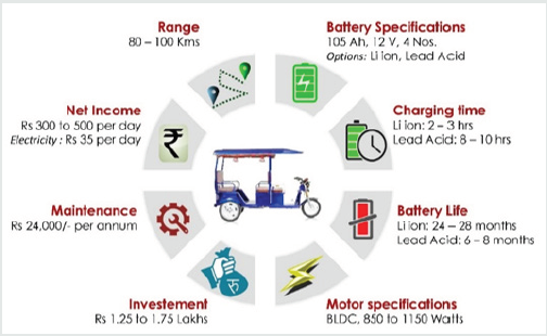
Figure 1: An Illustration of E-rickshaw specifications, investment and net-income.

Lupinepublishers-openaccess-Surgery-Casestudies

The electric rickshaws are powered by brushless dc motors ranging from 850-1150 watts and mostly produced either in China or India. An electric rickshaw offers a cheaper and eco-friendly transport facility to the low-income people [3]. An illustration of E-rickshaw specifications, investment and net-income is shown in Figure 1.

The major reasons for the rise of e-rickshaw are:
1. They require lower investment than an Auto-Rickshaw and quite pleasing daily earnings than cycle rickshaws.
2. They have lower running cost as E-Rickshaw charging is easily available with conventional single phase socket at home and low operating cost model for rickshaw owners.
3. E-Rickshaw is one of the best options for passengers for quick, safe and cost effective last mile connectivity.
4. They provide mass scale employment and good source of income to the traditional rickshaw puller.

Solar hybrid E-rickshaw

Solar hybrid electric rickshaw has a solar panel and runs up to 110 km per charge as an attractive alternative to the combustion engine driven auto-rickshaws. Solar energy is freely available sustainable energy which is converted into electrical energy by silicon plates fitted at the top of auto rickshaw for the sustainable energy future. A solar powered electric rickshaw provides a cheapest, cost effective, silent and pollution-free public transport for both rural and urban areas of India [3-4].

Methodology

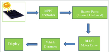
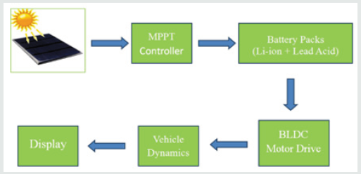
Solar Hybrid E-rickshaws are potential alternative in e-rickshaw segment owing to its extended range capability. For the purpose of understanding the concept of Solar Hybrid E-rickshaw, simulation and modeling is performed in MATLAB. Solar Hybrid E-rickshaw is easily analyzed by grouping models of different component namely E-rickshaw body, Solar Panel, MPPT controller, Battery Pack, BLDC Motor drive and display as shown in Figure 2 [5-8].

Figure 2: Block Diagram for Solar Hybrid E-rickshaw.

Lupinepublishers-openaccess-Surgery-Casestudies

Technical specifications

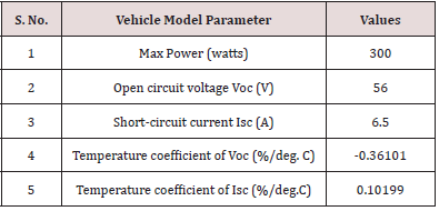
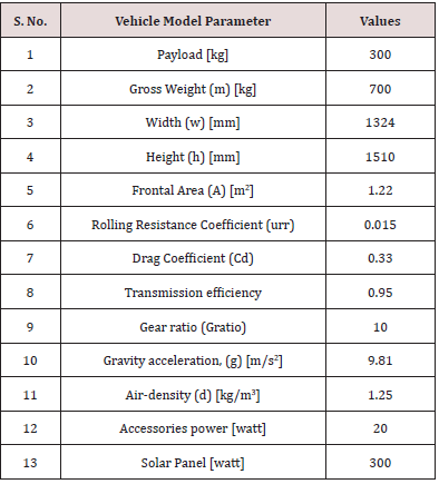
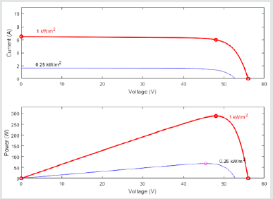
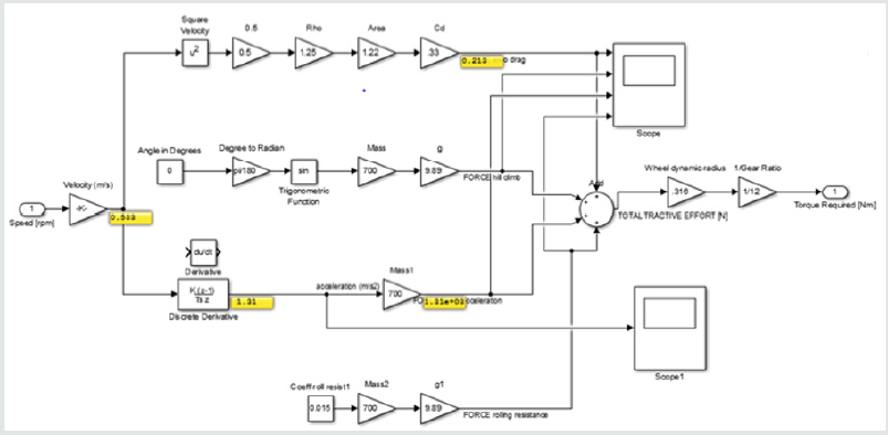
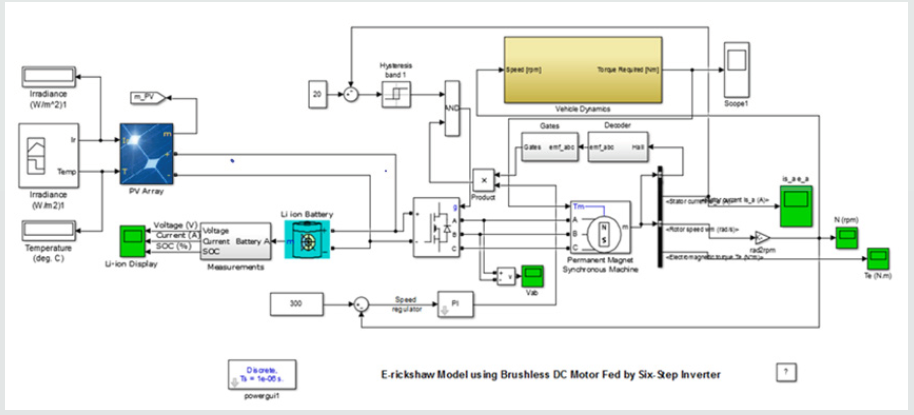
For modeling, solar panel parameters were taken as Table 1 and vehicle dynamics were taken as Table 2. The solar panel characteristic I-V and P-V curves are illustrated in Figure 3 and the SIMULINK model of solar hybrid E-rickshaw is shown in Figure 4 and the vehicle dynamics are represented in Figure 5.

Table 1:Solar Panel Parameters.

Lupinepublishers-openaccess-complementary-alternative-medicine-journal

Table 2: E-rickshaw Dynamics.

Lupinepublishers-openaccess-complementary-alternative-medicine-journal

Figure 3: Solar Panel Plots for I-V and P-V curves.

Lupinepublishers-openaccess-Surgery-Casestudies

Figure 4:Solar Hybrid E-rickshaw with Li-ion battery pack.

Lupinepublishers-openaccess-Surgery-Casestudies

Figure 5:E-rickshaw Dynamics Model.

Lupinepublishers-openaccess-Surgery-Casestudies

SIMULINK Models for Solar E-rickshaw with Heterogeneous Battery Packs

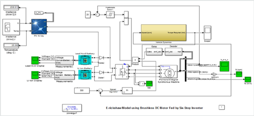
A new concept of using heterogeneous battery packs for electric vehicles is heard now-a-days for the sake of getting good battery life at reasonable price. In this work an attempt is made to visualize the effect of using simultaneous battery packs in Solar Hybrid E-rickshaw. The energy sharing of both the battery packs are monitored and analyzed. The block diagram of Solar Hybrid E-rickshaw with simultaneous battery packs is shown in Figure 6. The Li-ion battery has higher energy density than lead acid battery but costlier in comparison to latter. Therefore in this work an attempt is made to study the possibility of finding a reasonable heterogeneous battery pack for E-rickshaw. The SIMULINK model of solar hybrid E-rickshaw with heterogeneous battery packs is shown in Figure 7. The model consists of sub-blocks of solar panel with MPPT controller, Lead Acid battery pack, Lithium ion battery pack, Permanent Magnet Brushless DC motor, Vehicle dynamics, position sensor, Power Electronics Six-step Inverter and Speed controller. The energy flow under transient operation is simulated and analyzed.

Figure 6: Block Diagram for Simulation of Solar Hybrid E-rickshaw with Heterogeneous Battery Packs.

Lupinepublishers-openaccess-Surgery-Casestudies

Figure 7:Solar Hybrid E-rickshaw Model with Heterogeneous Battery Packs.

Lupinepublishers-openaccess-Surgery-Casestudies

Results and Discussion

Solar Hybrid E-rickshaw Simulation

Solar Hybrid E-rickshaw is simulated with Li-ion battery pack and the variations of Motor Current, battery pack Voltage, battery pack Current and State of Charge (SOC) are observed as shown in Figures 8 & 9.

Figure 8:Li-ion battery pack Voltage, Current and State of Charge (SOC in %).

Lupinepublishers-openaccess-Surgery-Casestudies

Figure 9:BLDC Stator Current.

Lupinepublishers-openaccess-Surgery-Casestudies

Results for Solar Hybrid E-rickshaw Simulation with Simultaneous Heterogeneous Battery Packs. In this part the solar hybrid E-rickshaw is simulated with both Li-ion and lead acid battery packs. The variations of Battery pack State of Charge (SOC), voltage and current are observed as shown in Figures 10 &11. The energy sharing for the simulation of solar hybrid E-rickshaw with heterogeneous batteries shows that that Li-ion battery shares higher energy during transient operating conditions.

Figure 10: Li-ion battery pack Voltage, Current and State of Charge (SOC in %).

Lupinepublishers-openaccess-Surgery-Casestudies

Figure 11: Lead Acid battery pack Voltage, Current and State of Charge (SOC in %).

Lupinepublishers-openaccess-Surgery-Casestudies

Conclusion

The concept of solar hybrid e-rickshaw is an important step toward sustainable green transportation system. Now-adays, government has a number of schemes for clean and green technologies and therefore solar hybrid e-rickshaw is a viable solution. In this work, E-rickshaw with solar photovoltaic panel is simulated both with single and simultaneous battery packs. It was observed from the simulation results that solar hybrid E-rickshaw with heterogeneous shows that Li-ion battery pack shares higher energy when simultaneously used with Lead acid battery pack. The results signify the possibility of implementing simultaneous battery packs at a reasonable cost price.

Acknowledgment

We sincerely thank the administration of Govind Ballabh Pant University of Agriculture & Technology, Pantnagar for their support. The financial support from TEQIP III, College of Technology, Pantnagar is also acknowledged.

Read More about Lupine Publishers Journal of Robotics & Mechanical Engineering Please Click on below Link: https://robotics-engineering-lupine-journal.blogspot.com/