Showing posts with label Journal of Material Science. Show all posts

Tuesday, 10 October 2023

Lupine Publishers | Post-Breast Cancer Chronic Wounds with Solid Calcifications Treated with Cu/SiO2-TiO2 Nano Biocatalyst

 Lupine Publishers| Journal of Modern Approaches on Material Science


Abstract

Objective: To describe patient outcomes with respect to the use of Cu/SiO2-TiO2 nanoparticles embedded in a polymeric gel as treatment for post-breast cancer chronic wounds with solid calcifications.

Methods: The nanoparticles were synthesized by the sol-gel method. The compound was incorporated into a polymeric gel matrix. SEM and TEM microscopy studies were carried out to evaluate grain size, morphology, and texture of the pure nanoparticles. The chronic wounds were treated by applying zinc oxide as emollient, Triticum vulgare (Italdermol®) and the Nano biocatalyst. The wound was covered with Solvaline® N dressings for the absorption of the exudate.

Results: The Cu/SiO2-TiO2 nanobiocatalyst displayed average particle size between 5 and 10 nm with high particle dispersion. Ordered arrangement of the nanoparticles was observed in TEM micrographs suggesting anatase crystalline structure. Microcalcifications extracted from the wound were suspected to be calcium carbonates and calcium oxalates, exhibiting sizes of the order of 20 μm. The administration of the nanoparticles with Triticum vulgare enhanced granulation tissue formation and revascularization by limiting bacterial infection. After 8 months of the first application the wound had completely healed in an atrophic scar, with no sign of inflammation or infection. No adverse effects were observed in the patient.

Conclusions: Post-breast cancer chronic wounds were successfully treated with Cu/SiO2-TiO2 nanoparticles. Good outcomes were observed in terms of tissue regeneration, wound healing, and infection hindering. Calcifications were eliminated. The nanoparticles can be used as a primary apposite to stimulate the autolytic debridement of injures due to their excellent local absorption and bactericide action.

Declaration of Interest: The study’s sponsors were not involved in the study design, the collection, analysis and interpretation of the data, the writing of this manuscript and the decision to submit this article for publication. The views express in this article are those of the authors.

Keywords: Cu/SiO2-TiO2, Chronic wounds, Breast cancer, Microcalcification, Tissue regeneration

Key Points:

a. A nanobiocatalyst based on mixed-oxides impregnated with transition metals was synthesized by the sol-gel method for the treatment of a post-breast cancer chronic wound.
b. The nanobiocatalyst presented displayed average particle size between 5 and 10 nm with high particle dispersion and ordered particle arrangement suggesting anatase crystalline structure as observed by SEM and TEM.
c. The post-breast cancer wound exhibited the formation of microcalcifications (20 μm) composed of calcium carbonates and calcium oxalates.
d. The administration of the nanobiocatalyst enhanced the formation of granulation tissue and revascularization by limiting bacterial infection.
e. The 30-years-old wound completely healed in an 8-months period, with no adverse effects detected.
f. The microcalcification formation was eliminated after tissue regeneration.

Introduction

Despite recent advances in the detection and treatment of metastatic breast cancer, mortality related to this disease remains as one of the highest due to the emergence of therapy-resistant cancer cells [1-5]. In 2018, an estimated 2 million new global cases were diagnosed representing 23% of all cancers, incidence rates varying from 19.3 per 100,000 women in Eastern Africa to 89.7 per 100,000 women in Western Europe [6]. By 2030, the number of deaths in Latin America is expected to achieve 74,000 per year [7]. The Globocan 2018 estimated that in Mexico the incidence for breast cancer was 39.5 cases per 100,000 habitants, with a total of 27,283 new cases and 6,884 deaths [8,9]. Common treatments for nonmetastatic breast cancer include endocrine therapy and cytotoxic chemotherapy [10]. The main surgical approach for cancer of the breast in all stages, early or late, is a radical and total mastectomy, breast-conserving surgery, and breast reconstruction, all followed by irradiation [11]. Possible side effects of surgery include seroma, hematoma, lymphoedema, cording, restricted range of movement in the shoulder, nerve pain, tissue necrosis, microcalcification formation, and surgical site infection [12-15]. The incidence of wound complications after breast cancer surgery are substantial, ranging from 6 to 30% [16-19]. There are several factors related to increased risk of complications in post-surgical patients, including patient risk factors (e.g., diabetes, obesity, and smoking), [20,21] surgical technique, [22] and type of surgery. [23] In fact, it has been suggested in previous studies that radiation increases the risk of complications, both in patients receiving breast implants, [24-29] and in those treated with autologous reconstructions. Murthy et al. [30-32] proposed that delayed wound healing is associated with an increased rate of systemic recurrence after primary breast cancer excisional surgery, [33] therefore one main point of attention in postoperative care must be the control of wound-closure-hindering infections.

In past studies, we have evaluated the healing properties of copper nanoparticles stabilized in a titania-silica mixed oxide matrix (Cu/SiO2-TiO2) as a treatment for chronic diabetic foot ulcers [34,35]. The nanoparticles prepared by the sol-gel process allowed to avoid a programmed supracondylar amputation in the patient, with favorable clinic evolution of the chronic ulcer by enhancing tissue regeneration and wound healing.

Aim of the Study

The aim of this study was to determine the wound healing properties of the Cu/SiO2-TiO2 nanoparticles for the management of breast-cancer-related chronic wounds in combination with Triticum vulgare (used as a treatment of oral mucositis by radiotherapy and chemotherapy in cancer patients) [36] and Solvaline® N (wound dressing).

Materials and Methods

Ethanol (99.8%), copper acetylacetone (97%), sulfuric acid (98%), phosphoric acid (98%), tetraethyl orthosilicate (98%) and titanium butoxide (98%) were purchased from Sigma Aldrich Company (Saint-Louis, MO, USA). Solvaline® dressings were purchased from Lohmann & Rauscher (Milwaukee, WI, USA), and aqueous extract of Triticum vulgare (Italdermol®) was obtained from Italmex (Mexico City, CDMX, Mexico).

Preparation of Cu/SiO2-TiO2 Nanoparticles

The nanoparticles were synthesized following the procedure of secrecy No. 101/100/014/13. A flask with deionized water and ethanol was kept at room temperature and constant stirring, the adequate amount of copper acetylacetonate was added to this mixture, then the pH was adjusted to pH 1 with sulfuric and phosphoric acids. During a period of 4h, tetraethyl orthosilicate and titanium butoxide were added dropwise to the mixture under stirring. Once the alkoxides were completely added, the temperature was increased while stirring until gelation. The nanoparticles were obtained when the gel dried. The compound was incorporated into a polymeric gel matrix.

Scanning and transmission electron microscopy studies

The grain size, morphology, and texture of the pure nanoparticles with no polymeric gel matrix were characterized by scanning electron microscopy (SEM) in a JEOL JSM-6010LV microscope equipped with an energy dispersive spectroscopic (EDS) microanalysis system (OXFORD). The nanoparticles’ size was determined by transmission electron microscopy (TEM) in a JEOL JEM-2100F, operated at 120 kV voltage. The images were obtained using a CCD Mega Vision (III) camera.

Clinical Study

Patient Clinical History

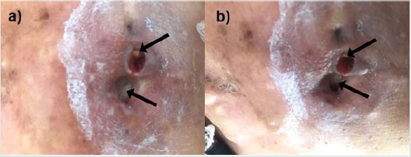
A 78-years-old female patient from Mexico City presents a family history of diabetes mellitus and hypertension, as well as cases of chronic venous insufficiency and deep vein thrombosis, from both mother and father lineages. She presents type-2 diabetes mellitus for 15 years treated with biguanide and insulin 30-0-20, with medication non-adherence problems. The patient refers previous history of mixed dyslipidemia and hypertension. Furthermore, the patient was diagnosed with Invasive Ductal Carcinoma (IDC) in the left breast thirty years ago, which conducted to total mastectomy and irradiation. The breast cancer exhibited total remission for 30 years. The patient reported to medical consultation for presenting small wounds in the chest and secondary calcifications that were growing inside and outside the injury since the beginning of irradiation therapy. During first physical exploration blood pressure was 140/90 mmHg, heart frequency had a rate of 76 beats per minute, respiratory rate of 18 breath per minute, temperature was 36.9°C. The patient denies fever, general discomfort, asthenia, and adynamia. The size of the wound located in the left thorax is 2.0 x 1.0 x 1.5 cm with macerated borders (Figure 1a&1b), the perilesional skin showed edema, erythema, and hyperpigmentation, with yellow exudate and foul odorous suppuration, visible calcifications were identified inside the wound. She exhibits a scar due to the previous total mastectomy of the left breast. The patient refers moderate pain at palpation and during wound cleaning.

Figure 1: Post-breast cancer chronic wound with solid calcifications. The size of the wound is 2.0 x 1.0 x 1.5 cm with macerated borders. Calcifications are identified with black arrows.
Lupinepublishers-openaccess-material-science-journal

Clinical Diagnosis

Chronic radiation-induced ulcer in the chest wall after surgery in breast cancer. Risk factors for systemic recurrence: female, total mastectomy, chronic untreated ulcers, type-2 diabetes mellitus, hypertension.

Treatment

Advanced wound care was initiated by applying zinc oxide (ZnO) on the macerated skin due to its epithelialization and infection-control properties [37]. The Cu/SiO2-TiO2 nanoparticles embedded in a polymeric matrix were applied in combination with Triticum vulgare inside the wounds to generate granulation tissue and limit bacterial infection. The wound was covered with Solvaline® N dressings for the absorption of the exudate. Additional management included prophylaxis antibiotics on one occasion and analgesics each 12 hours when pain was presented.

Results

Electronic Microscopy Studies Of The Nanoparticles

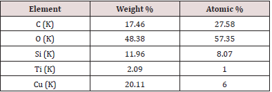
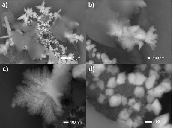
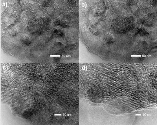
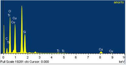
SEM images showed Cu/SiO2-TiO2 nanoparticles formed conglomerates with visible crystalline structure and average particle size between 0.1 and 1 μm, as shown in (Figure 2a). The conglomerates exhibit a flake morphology with a flustered arrangement of the nanoparticles. A deeper analysis increasing magnification to 37,000x (Figure 2b), 70,000x (Figure 2c), and 100,000x (Figure 2d) allowed to observe individual nanoparticles with sizes ~ 10 nm grouped in 100-nm conglomerates. A further study of TEM (Figure 3) allowed to corroborate individual particle size to be of the order of 5 nm. Particle arrangement observed in TEM images suggest the presence of crystalline structure, possibly microcrystalline anatase with grain sizes of 10-30 nm as observed in previous XRD studies regarding the SiO2-TiO2 mixed oxide matrix [38-40] (the diffractograms are not shown in this paper for the sake of brevity). EDS measurements in the conglomerates showed homogeneous distribution of the elements present in the compound with atomic percentages as expected (Figure 4). The atomic composition is shown in Table 1.

Table 1: Atomic percentage composition of the nanoparticles.
Lupinepublishers-openaccess-material-science-journal

Figure 2: SEM micrographs of the Cu/SiO2-TiO2 nanoparticles at 15,000 x (a), 37,000 x (b), 70,000 x (c), and 100,000 x (d). Nanoparticle conglomerate formation with sizes 0.1–1.0 μm is observed. Individual nanoparticles exhibit average particle size of 5-10 nm.
Lupinepublishers-openaccess-material-science-journal

Figure 3: TEM micrographs of the Cu/SiO2-TiO2 nanoparticles with dimensions 50 nm (a, b) and 10 nm (c, d). Individual particle size was identified to be < 10 nm. The nanoparticles exhibit crystalline structures with grain sizes of 10-30 nm. Particle arrangement suggests an anatase crystalline structure.
Lupinepublishers-openaccess-material-science-journal

Figure 4: EDS measurement in the conglomerates with the presence of Ti, Si, O, and Cu, elements that compose the Cu/SiO2-TiO2 nanoparticles. Carbon peaks correspond to the carbon tape in which the sample was placed.
Lupinepublishers-openaccess-material-science-journal

Microcalcification Analysis

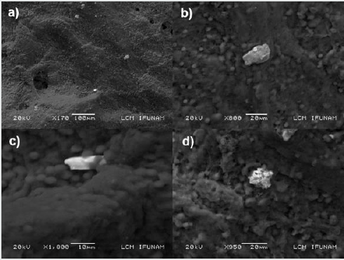
Microcalcification accompanies several benign and malignant alterations in breast parenchyma [41,42]. Most commonly the calcifications (5 μm to 100 μm) are composed of hydroxyapatite (Ca10(PO4)6(OH)2), which forms concentric concretions and amorphous masses, [43] exhibiting grey-white, opaque, and ovoid form or fusiform shapes with irregular surfaces [44]. Less often, calcium oxalate dihydrate (Weddellite) is deposited, forming single crystals up to 1 mm long, [44,45] which are amber in color, partially transparent and form pyramidal structures with relatively planar surfaces [46]. Before treatment with Cu/SiO2-TiO2 nanoparticles and Triticum vulgare, the wound was cleaned, and intern calcifications were removed. After a few applications, internal calcifications emerged from the wound, which captured our attention. For a better understanding of the properties of the calcifications obtained, the crystals were analyzed by SEM and EDS techniques to identify morphology, texture, and composition. In (Figure 5) a sample of epithelial tissue is observed with the presence of individual calcifications with sizes of the order of 20 μm. The masses exhibit amorphous structures with no visible presence of crystal twinning. According to bibliography revised, [15,43-45] our hypothesis is that the calcifications are composed of calcium carbonate (CaCO3), calcium oxalate (Ca(CO2)), or hydroxyapatite (Ca10(PO4)6(OH)2); the aforementioned is intended to be corroborated in a further EDS study. Calcium oxalate has been shown to be associated with benign lesions of the breast or at most non-invasive lobular carcinoma in situ [47]. Calcium carbonate microcalcifications identified with breast tissues grow in calcite and aragonite crystal structures [48].

Figure 5: SEM micrographs of the calcifications observed in the wound-tissue sample. Individual calcifications with sizes of the order of 20 μm are observed surrounded by erythrocytes deposited in the surface of the epithelial tissue.
Lupinepublishers-openaccess-material-science-journal

Clinical Study

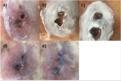
Administration of Cu/SiO2-TiO2 nanoparticles with Triticum vulgare enhanced granulation tissue formation by limiting bacterial infection as early as two months after the first application. The wound was dry and clean, with sharp edges and edema reduction. After four months of treatment, the size and depth of the chronic wound had reduced significantly, presenting an erythematous clean bed and a decrease in calcification formation. At the 6-months mark, granulation tissue was observed with optimal reepithelization and no fibrin due to revascularization and fibroblast production. After 8 months of the first application, the wound has completely healed in an atrophic scar. No inflammation was observed. The healing process is observed in (Figure 6).

Figure 6: Evolution of the chronic wound with Cu/SiO2-TiO2 + Triticum vulgare treatment at time 0 (a), after 2 months (b), after 4 months (c), after 6 months (d), and after 8 months (e). The white film observed corresponds to the zinc oxide applied as emollient.
Lupinepublishers-openaccess-material-science-journal

Discussion

The clinical case presented several risk factors that seriously complicated the wound healing process and represented a possible systemic recurrence: chronic untreated ulcers, hypertension, and type-2 diabetes mellitus. In healthy patients, the healing process involves coordinated interactions between diverse immunological and biological systems, which are divided into four time-dependent steps: (i) coagulation and hemostasis, (ii) inflammation, (iii) proliferation, and (iv) wound remodeling [49-55]. The four steps are essentially dependent on a proper blood irrigation to the wound for the transport of the cells (endothelial, thrombocytes, neutrophils, etc.), nutrients, and coagulation and inflammatory factors that will intervene in the process [56-59]. Diseases that lead to compromised microcirculation, such as diabetes, inhibit the delivery of oxygen and nutrients to tissue injuries, impairing wound healing [60] and causing the development of chronic wounds on account of impaired growth factor production, angiogenic response, collagen accumulation, fibrosis, and abnormal blood pressure [61]. Furthermore, due to chemotaxis and impaired leukocyte function and inadequate migration of neutrophils and macrophages to the wound, [62-64] diabetic patients develop a preponderance for infections such conditions demand for wound healing treatments that enhance reepithelization while reducing infection progression [65,66].

Titania-silica mixed oxide nanoparticles with high specific surface areas (up to 645 m2/g) have been studied regarding their catalytic properties for a broad variety of applications, [38,40,67- 69] including absorption of organic pollutants, [70] drug delivery, [71,72] and catalysis [73-75]. The incorporation of transition metals (such as platinum and copper) in the mixed matrix has been reported to enhance the antibacterial properties of the compound. [34,35] For the treatment of the chronic wounds the patient exhibited, we synthesized Cu/SiO2-TiO2 nanoparticles with catalytic and antibacterial properties. The nanoparticles were obtained by the sol-gel process through a hydrolysis catalyzer to achieve acid conditions in the gelation process, and thus, to obtain acid nanomaterials. The development of acidic properties in binary mixed metal oxides in terms of Lewis and Brønsted acidic sites has a direct impact on the catalytic properties of the nanoparticles. [38,76,77] The nanoparticles’ size observed in SEM and TEM studies (5-10 nm) makes them capable to traverse the plasmatic membrane of the bacteria through passive diffusion [78]. Once inside the bacteria, due to synthesis method used and their functionalized surface, the nanoparticles are able to catalyze the breakage of C-C and C-N bonds present in DNA and RNA nitrogenous bases hence destabilizing the structure of the molecule and inhibiting the bacterial reproduction [79]. This biocatalytic process is believed to generate molecular oxygen which enhances the proliferation of fibroblast activity, [80] collagen synthesis, [81] and inflammation, [82] hence improving the generation of granulation tissue and reepithelization, and significative decreasing the time of recovery.

The patient’s wounds treated with the Cu/SiO2-TiO2 nanoparticles exhibited total recuperation after 8 months since the first application. Through the healing process, internal solid calcifications emerged from the wound. They were removed and analyzed by SEM technique. The presence of calcium compounds in the breast is related to benign lesions, as the chronic wounds the patient exhibited. After the application of the nanoparticles, the calcification formation was reduced and eliminated as a sign of lesion recovery [41,83]. The successful outcome achieved with the treatment meant a significant improvement in the patient’s quality of life, eliminating the possibility of a systemic recurrence of breast cancer [18].

Conclusion

Post-breast cancer chronic wounds were successfully treated with Cu/SiO2-TiO2 nanoparticles in a patient with the menace of systemic recurrence due to risk factors such as hypertension and type-2 diabetes mellitus. Good outcomes were observed in terms of tissue regeneration and wound healing. The therapy with the nanoparticles embedded in a polymeric gel hindered infection formation allowing wound reepithelization and healing with a time of recuperation significantly reduced (8 months in a 30-years-old chronic wound). Furthermore, calcifications present in the wound were removed and the recurrent formation was eliminated after the treatment. No adverse effects were observed in the patient. Scientific evidence supporting the efficacy and safety of the Cu/ SiO2-TiO2 therapy is hereby shown. The nanoparticles can be used as a primary apposite to stimulate the autolytic debridement of injures, due to their physical-pharmaceutical properties: excellent local absorption because of its nanoparticulate composition and bactericide action that helps control local infections. Yet, future studies must be carried out to further confirm the efficacy of the nanoparticles.

Reflective questions

a. Microcalcification formation elimination is related directly with the catalytic effect of the nanoparticles or with the wound healing process?

b. Do we need to assess the effectiveness the nanobiocatalyst in the real world and not simply rely on clinical trial data?
c. What can be done to improve wound healing rates?
d. How can the efficiency of health-care delivery be improved?

Author Contribution

All authors contributed to the study conception and design. The design and synthesis of the nanoparticles were executed by TL, PR and FJPG. The characterization techniques were made by EGL. The patient’s treatment was carried out by VSB. The first draft of the manuscript was written by FJPG. All authors commented on previous versions of the manuscript and critically revised it. FJPG was responsible for compiling the final draft. All authors read and approved the final draft.

Funding

This study was funded by the Autonomous Metropolitan University – Xochimilco and NANOTUTT S.A. de C.V.

Compliance With Ethical Standards

Conflict of Interest: The authors declare that they have no conflict of interest.

Ethics Approval: This study was performed in line with the principles of the Declaration of Helsinki. Necessary ethical clearance was obtained from the ethical committee office code number JUDI- 01/07 CDMX under the protocol: [“Security and efficacy of the local application of Pt/SiO2-TiO2 nanomaterials in patients with diabetic foot ulcers” Education and Investigation Direction], and the study was conducted in accordance with the ethical Good Clinical Practice.

Declarations

Consent to participate. Informed consent was compulsory for contribution in the study. The staff notified the contributor with the objectives, dates, drugs, diet, possible risks, and general activities through the clinical study.

Consent to Publish: No personal data of the patients was mentioned in the study.

ORCID ID

1. Tessy López: https://orcid.org/0000-0002-6048-0419
2. Francisco J. Padilla-Godínez: https://orcid.org/0000- 0002-9253-2463

Read More About Lupine Publishers Journal of Modern Approaches on Material Science Please Click on the Below link:

https://lupine-publishers-material-science.blogspot.com/

Tuesday, 15 August 2023

Lupine Publishers | Impact of Low Frequency Vibration During Welding and Annealing on Microstructure of Mild Steel Butt-Welded Joints

 Lupine Publishers | Journal of Modern Approaches on Material Science


Abstract

This work examined the Impact of Low Frequency Vibration during Welding and Annealing on Microstructure of low carbon steel Butt-welded Joints with a view to establishing vibration regimes and the resultant microstructures that may improve the condition of service performance as well as increasing life span of welded joints. Commercially available mild steel plates were butt-welded employing vibration and non-vibration welding conditions and subjected to heat treatment before carrying out metallographic analysis. Vibration frequencies were varied from 0 to 14.32Hz in three different steps.The mechanical performance of the weldment with reference to strength and toughness depend upon the type of microstructure of weld metal and heat affected zone. The post weld heat treatment of annealing and stress relieving tend to significantly reduce the incidences of the conditions highlighted above. Also, rearrangements and realignments of the grains especially at the weld zones are obvious and have greatly influenced the quality and properties of the welded joints. It was observed from the vibrated frequencies 7.96Hz and 14.32Hz that the grain size diameters are coarser in the non-heated samples than the annealed samples in all the investigated zones. Hence, the vibration treatment during welding and casting greatly influence microstructures and improves grain refinement and service performance of the butt-welded joints.Results of microstructure analysis indicates fine-grained sizes at weld zones; but coarse at the heat affected and base metal zones, respectively. Therefore, microstructures having finer grain sizes are known to possess good mechanical properties with consequential effect on fracture toughness.

Keywords: Butt-Welded; Grains; Microstructure; Coarse; Weldment; Annealing; Vibration

Introduction

As a result of the availability, ease of fabrication, cost, good mechanical properties, and weldability of Low carbon steel; it has found diverse applications in transportation, marine, mining, chemical processing, pipelines, construction, and metal-processing equipment. Most of the engineering components are being joined through various techniques which include welding, fastening, riveting, brazing. However, welding process has been adopted for several manufacturing processes to minimize manufacturing time, achieve weight reduction, improve mechanical attributes and to ensure permanent joint [1]. Welding is essentially a metal joining technique. A weldment can be grouped into three distinct zones which are weld metal zone (WMZ), heat affected zone (HAZ) and the unaffected base metal zone (UBMZ). For low carbon steel which is the most welded material the three zones of a weldment can be indicated in an iron carbon equilibrium diagram [2].The fusion zone which is the volume of the parent metal melted to form part of the weld metal zone or the weld head lies between the WMZ and HAZ [3].The weld metal zone is formed by the solidification of the weld pool which itself is formed by the melting of a part of the parent metal and the additional material that is contributed by the melting of the electrode when used. In welding, however, there is a gradual change in temperature from the center of the weld pool to a short distance away from it, solidification of the molten metal in the weld pool starts as soon as it reaches the liquidus temperature for that material composition [3]. It requires no undercooling as the party melted grains provide the nuclei where from the growth of grains start into the solidifying weld pool, such a mode of solidification is referred to as Epitaxial solidification [2].

Properties most required of weld metal are toughness and strength. In general strength and toughness of the weld metals do not match those of corresponding base on parent metal. The ratio of yield strength to ultimate tensile strength is always higher in weld metal than in base metal [4]. Properties of weld metals are greatly influenced by the type of microstructure, grain size, precipitation processes, ageing, etc. in a similar vein; microstructure can be affected considerably by welding parameters like welding speed, heat input, etc. Toughness properties of weldments are worse than those of rolled or forged steels, in addition to strength and toughness, weldments are also required to have good fatigue properties [5]. In general fatigue properties of weld metals are interior to those of corresponding base metals. Because fatigue properties are affected mainly by weld contours as well as by morphology and dispersion patterns of inclusions. Therefore, to obtain good fatigue properties, weld metals must be sufficiently pure. Also, because of a lower carbon content it welds metal in comparison with that in the steel forming the HAZ and the base metal, the creep strength of the weld metals is always lower. Therefore, it can be said that the weld metal properties are affected not only by the chemical composition of the filter material used, but also by the chemical composition of the steel used as the parent material, the welding process employed and the weld cooling rates [6].A heat affected zone of a weld is that part of the welded joint which has been heated to a temperature up to the solidus of the parent material resulting in varying degree of influence on microstructure as a consequence of heating and cooling cycle [7]. When metal and alloys without polymorphous transformation (e.g. Cu, Ni, Ai) are welded, the microstructure in the HAZ remains unaltered though grain growth or recrystallization may take place while in the case of metals and alloys with polymorphous transformations (e.g. steels), significant micro structural changes take place in HAZ, that in turn influence the mechanical properties and consequently the service behaviour of the welded joint [5].This study therefore seek to investigate the effectof low frequency vibration during welding and annealing on microstructure of mild steel butt-welded joints of low carbon steel with a view to establishing vibration regimes and the resultant microstructures that may improve the service performance andincrease thelife span of welded joints.

Method

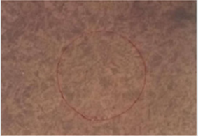
Butt-welded joints of O Hz, 7.96 Hz and 14.32 Hz were made up of three distinct zones such as parent metal, heat affected zone and weld zone. From each sample, sections were obtained using manual hack sawing which were representatives of all the segments of the samples. Because the specimens were small, hence they were mounted to facilitate rough grinding as well as intermediate and final polishing. Each extracted sample was ground using silicon carbide belt grinders of finer silicon carbide with grits of 240, 320, 400 and 600 meshes. Final grinding was carried out with 1000 grit size silicon carbide grinder. Each sample was then polished using Magnesium Oxide (MgO) powder. The mirror-like blower was dried using an electric blower and etched using a solution composed of Nital 2% (that is 2% Nitric Acid and 95% methyl alcohol). Etching revealed the different welded zones when viewed under the optical microscope and with the aid of the digital camera mounted on the microscope, the photomicrographs of the various structures were obtained. For the grain size measurement, the circular intercept method was employed whereby a circle of diameter 79.8mm was drawn on each micrograph representing the three zones of the weld joints. This circle was counted and added to ½ the intersecting grains. The number was then further translated as an average grain diameter of each photomicrograph. This was determined for all the weld zones and heat affected zones (HAZ) respectively

Results and Discussion

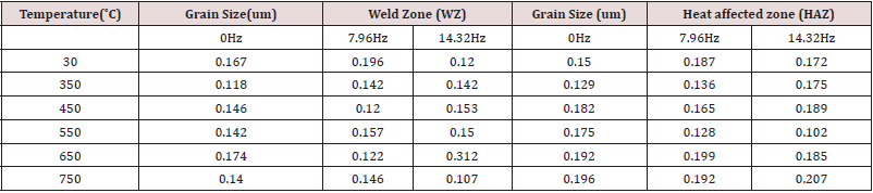
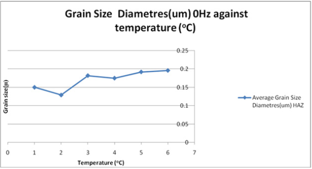
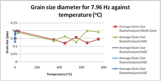
Results of microstructure analysis are presented in plates 1 -15 while the grain size diameters at different vibrations are presented in (Figures 1-3) and Table 1 Discussion

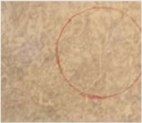
Plate 1: A1 Welded Zone for Control Sample (X250).

Lupinepublishers-openaccess-material-science-journal

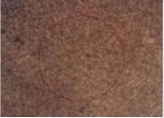
Plate 2: A1 HAZ for Control Sample (X250).

Lupinepublishers-openaccess-material-science-journal

Table 1: Variation in Temperature with Grain size, Weld Zone and Heat Affected Zone.

Lupinepublishers-openaccess-material-science-journal

Figure 1: Grain Size Diameters for 0Hz Vibration Frequency.

Lupinepublishers-openaccess-material-science-journal

Figure 2: Grain Size Diameters for 7.96Hz Vibration Frequency.

Lupinepublishers-openaccess-material-science-journal

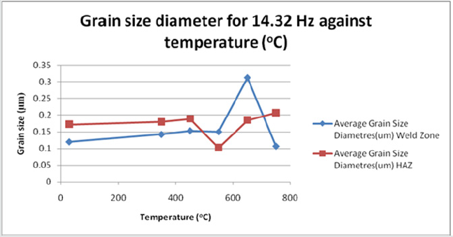
Figure 3: Grain Size Diameters for 14.32Hz Vibration Frequency.

Lupinepublishers-openaccess-material-science-journal

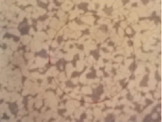
Plate 3: A1 Welded Zone Annealed at 350˚C.

Lupinepublishers-openaccess-material-science-journal

Plate 4: A1 HAZ Annealed at 350˚C(X250).

Lupinepublishers-openaccess-material-science-journal

Plate 5: A1 Welded Zone Annealed at 450˚C(X250).

Lupinepublishers-openaccess-material-science-journal

Plate 6: A1HAZ Annealed at 450 ˚C(X250).

Lupinepublishers-openaccess-material-science-journal

Plate 7: A1 Welded Zone Annealed at 650.

Lupinepublishers-openaccess-material-science-journal

Plate 8: A1 HAZ Annealed at 650˚C (X250).

Lupinepublishers-openaccess-material-science-journal

Plate 9: A1 Welded Zone Annealed 650 ˚C(X250).

Lupinepublishers-openaccess-material-science-journal

Plate 10: A1 Welded Zone Annealed at 750 ˚C(X250).

Lupinepublishers-openaccess-material-science-journal

Plate 11: HAZ Annealed at 750 ˚C(X250).

Lupinepublishers-openaccess-material-science-journal

Plate 12: A2 - Welded Zone Control Sample (X250).

Lupinepublishers-openaccess-material-science-journal

Plate 13: HAZ Control Sample (X250).

Lupinepublishers-openaccess-material-science-journal

Plate 14: A2 Welded Zone Annealed at 350˚C(X250).

Lupinepublishers-openaccess-material-science-journal

Plate 15: A2 Welded Zone Annealed at 350˚C(X250).

Lupinepublishers-openaccess-material-science-journal

Microstructure of Samples Vibrated at 0Hz Frequency

Weld Zone (Non – heat treated sample): The microstructure consists of light areas and dark areas. The light areas represent ferrite while the dark areas represent pearlite grains. Generally, the structure is that of chunky pearlite in partially transformed zone. Etching reagent of 2% Nital was used at 250X magnification. For the heat affected zone of the non-heat-treated samples, the microstructure was etched in 2% Nital at 250X magnification. There is distribution of fine pearlite grains as dark spots in a martensitic matrix. There is also the presence of small white undissolved carbide spheroids in dark pearlite areas. The weld zone annealed at 3500C reveals a fine dispersion of pearlite, otherwise called alloy carbides in a matrix of ferrite grains. The ferrite grains occupy the light back-ground. The microstructure was etched in 2% Nital solution at 250X magnification. Heat affected zone annealed at 3500C, the sample was welded under normal welding condition without application of vibration frequency. The microstructure etched in 2% natal consists of polygonal ferrite and acicular ferrite. The dark areas connote pearlite. The structure reveals that the cooling was slow as the sample was cooled in the furnace which resulted in tempered bainite [8]. The weld zone produced under normal welding condition and heat treated at 4500C was slowly cooled in the furnace. The structure consists of fine-grained pearlite and ferrite signs of non-metallic inclusions seen as dark cuts. Etching solution of 2% natal was used at 250X magnification. For the heat affected zone at the same heat treatment temperature and under the same welding condition, large pearlite and ferrite grains can be observed together with the evidence of grain growth.
The structure was etched in 2% natal at 250X magnification. The weld zone heat treated at 5500C and under the same welding condition of 0Hz frequency consists of fine ferrite grains which are depicted in white areas with equal amount of pearlite grains which are in dark areas (Figure 1). The presence of large dark spots indicates inclusions. It is also an indication that the weld was defective. The heat affected zone at the same temperature of 5500C shows tempered bainite with some proeutecoid ferrite. More equiaxed light gray constituents can also be observed in the sample [9]. The structure was revealed when etched in 2% natal at the magnification of 250X. The weld zone heat treated at 6500C under the same welding condition largely contain sepitacial grain structure; acicular or lower bainite; and black needles in a martensic white matrix etched in 2% natal and at 250X magnification. At the same annealing temperature of 6500C, the resulting microstructure is that of spheroidized carbides in a ferrite matrix. The structure was etched in 2% natal. The weld zone heated at 7500C, furnacecooled to room temperature and treated to no vibration frequency showed a structure of the fine spheroidal cementite in a matrix of ferrite. The heat affected zone on the other hand clearly showed grain growth zone. The microstructure consists of pearlite carbides prominent within the soft ferrite matrix.

Microstructure of Samples Vibrated at 7.96Hz Frequency

The weld zone produced at 7.96Hz vibration frequency has a structure of epitaxial long grains with large dark spots occasioned by welding defects (Figure 2). As a result of the vibratory treatment, the grains are more aligned. The microstructure consists of long ferrite grain with dark boundary edges. The heat affected zone consists of ferrite and pearlite grains. Large white portions represent the ferrite grain while the dark portions represent the ferrite grain while dark pearlite grains. The microstructure was etched in 2% nital at 250x magnification. The weld temperature of 3500c under the vibratory condition of 7.69Hz frequently showed a fine dispersion of carbide in ferrite matrix. The light areas are ferrite grain whereas the dark areas are pearlite grains [10]. Etching reagent used is 2% nital at 250x magnification. For the heat treatment temperature of 3500c, the microstructure consists of pearlite-ferrite grains. The appearance of the structure depicts tempered martensite. At 4500c, the weld zone has a structure of refined equiaxed grain. There are no contaminants in the structure. The weld joint is sound etched in 2% nital, the heat affected zone at 7.69Hz vibration frequency and 4500c heat treatment temperature has a structure consisting of pearlite and ferrite with pearlite scattered in ferrite matrix. The microstructure does not significantly change from the structure of the base metal. Both ferrite and pearlite are evenly distributed. Etchant of 2% nital was used. The weld zone heat treated at 5500C and at the same vibration has a structure of ferrite and cementite. The cementite grains became elongated with maximum ductility and minimum hardness with reduced machinability [6].
On the other hand, the heat affected zone consists of fine-grained ferrite and pearlite of spheroidal shapes. The heat affected zones in a most of the residual and welding stresses have been removed. The microstructure was etched in 2% initial. The weld zone heated to austenitizing temperature and annealed below sub-critical temperature consists of fine-grained ferrite and small pearlite areas. The structure has good impact toughness and strength but moderately hard, the heat affected zone at same temperature of 6500C consists of coarse grains of ferrite and pearlite with the pearlite zones subsumed in ferrite matrix. The weld zone heat treated to 7500C and vibrated at 7.96Hz welding frequency showed spheriodized cementite in ferrite matrix. All microstructure was studied using 2% nital as etchant and at the magnification of 250X. The heat affected zone slightly experienced thermal cycle from fusion zones. The microstructure basically consists of pearlite and ferrite but with large sizes of pearlite grains [11].

Microstructure of Samples Vibrated At 14.32hz Frequency

The microstructure for non-heat-treated samples showed equiaxed ferrite grain of a homogenous nature with pearlite patches within the matrix (Figure 3). The heat affected zones also contains pearlite and ferrite, grains of pearlite particles are coarse with pearlite being distributed in ferrite matrix. The structure is not distinct from the base metal structure. At 3500C heat treated temperature the microstructure consists of dense and massive ferrite grains with pearlite at the edges of the ferrite grains. In the heat affected zones on marked microstructural changes recorded. The structure cooled slowly to coarse grains of ferrite and pearlite while dark areas are pearlite. The weld zoneheat treated to 4500C consist of tempered martensite whereasthe heat affected zone has a structure of fine lamellar pearlite and ferrite the hardness of the base metal and the structure is not remarkably different from the original structure [11]. The weld annealed at 5500C and cooled in furnace also consists of pearlite and ferrite with some spheroidal cementite [7]. The heat affected zones annealed at sub-critical temperature of 6500C consists of equiaxed ferrite grains with signs of entrapped gases.Black spots are alloy carbides with matrix of ferrite. The microstructure of the heat affected zone consists of ferrite and pearlite. The grains are large on sizes but shows portions of fine grains towards the unheated zone [10].

Effect of Vibration and Heat Treatment on Microstructure

The microstructure of the three zones were studied for all the specimens vibrated at frequencies of 0, 7.96 and 14.32 and annealed at temperatures 3500C–7500C (Plates 1-15). The specimens were initially subjected to moderate vibration frequencies of 0, 7.96 and 14.32 Hz. A common phenomenon of the microstructures studied was the presence of pearlite in ferrite matrix. At 0Hz the grains at the base metal and heat affected zone are coarser than at the moderately higher frequencies of 7.96 and 14.32Hz at the same zones. Grain sizes at the weld zones are more refined which may improve quality and performances of welded joints. Most grains are equiaxed and spheroidal at weld zones. The grain sizes of the weld zones are often evenly distributed with massive grains of pearlite and ferrite whereas coarse grains are observed in the structure of the base metal and the heat affected zones [7].Mostly the grains are fine at the weld zones. Under the normal welding condition, the grains of the non-heat-treated samples are of finer grain sizes than the heat-treated samples with respect to the weld zones and the heat affected zones. But at the moderately vibrated frequencies 7.96Hz and 14.32Hz the grain size diameters are coarser in the nonheated samples than the annealed samples in all zones studied. The study has indeed shown that vibration treatment during welding and casting can greatly influence microstructures and generally improves grain refinement and service performance of the buttwelded joints [12-15].

Effect of Vibration and Heat Treatment on Grain Size

For most steels, the grain size of the microstructure is a strong determinant of notch toughness Table 1. Vibratory treatment has been shown to improve grain refinements [6]. As a result, the grain size has marked influence on the yield stress, and strain hardening rate and it is therefore logical to expect grain size to influence fracture toughness. Therefore, microstructures having finer grain sizes are known to possess high mechanical strength with consequential effect on fracture toughness [11].

Conclusion

The heating and cooling cycles of welding result in the development of residual stresses. The residual stresses developed due to welding being a combination of tensile and compressive stresses. Different welding processes result in different rates of cooling with consequential effect on microstructure, grain size and residual stresses. A high cooling rate process like EAW results in fine-grained weld zone of high hardness and strength, but with low impact strength. The post weld heat treatment of annealing and stress-relieving tend to significantly reduce the incidences of the conditions highlighted above. On the other hand, a low cooling rate process like submerged arc welding results in comparatively coarser-grained weld zone of medium hardness and strength with high fracture toughness. As the weld zone and HAZ have different hardness so is their tendency to brittle fracture which is a major function of the composition of the microstructure that influences the mechanical properties of the weld metal[16-19].


Read More About Lupine Publishers Journal of Modern Approaches on Material Science Click on the Below Link: https://lupine-publishers-material-science.blogspot.com/

Tuesday, 20 June 2023

Lupine Publishers | An Investigation of the Effects of Surface Treatment on the Fatigue Property of Titanium Alloy for Femoral Stem and Bone Fracture Fixation

 Lupine Publishers | Modern Approaches on Material Science


Abstract

Titanium alloy (Ti6Al4V) is used for medical prosthetic devices and implants. This study investigated the effect of three types of surface treatments on fatigue and tensile properties of the metal. Representative samples were treated using polishing and chemical passivation using hydrogen peroxide and nitric acid. The surfaces of the treated and untreated samples were observed under an optical microscope and then the samples were subjected to tensile and tensile-fatigue tests using an Instron Servo-Hydraulic machine. The mechanically polished samples had 17% higher fatigue life than untreated samples. In contrast, the hydrogen peroxide and nitric acid treated samples had 5% and 7% lower fatigue life than untreated samples, respectively. Etched grain boundaries were observed on the surface of treated samples. It was concluded that when the samples were subjected to cyclic tensile load, the etched grain boundaries acted as crack initiation points and resulted in low fatigue life. Mechanical polishing on the other hand removed surface damages that could initiate fatigue failure and thus the polished samples had higher fatigue life. Hence, chemical passivation using hydrogen peroxide and nitric acid was unfavorable while polishing was favorable for enhancing fatigue life of the titanium alloy.

Keywords: Fatigue; titanium alloy; surface treatment; biomaterials

Abbreviations: MRI: Magnetic Resonance Imaging; HCF: High Cycle Fatigue; LCF: Low Cycle Fatigue

Introduction

Many metallic biomaterials composed of nontoxic and allergy-free elements have been developed in the recent years. Generally, all metal implants must be non-magnetic and high in density, to be compatible with magnetic resonance imaging (MRI) techniques and visible under X-ray imaging [1]. Titanium and its alloys are commonly used materials for this purpose as they have low specific gravity, excellent corrosion resistance and strength, high biocompatibility, and are non-magnetic. With these advantageous features, titanium is an optimum material for medical prosthetic devices.Approximately one million patients worldwide are treated annually for total replacement of arthritic hips and knee joints, whereas numerous numbers of patients use various devices for bone fracture fixations [1]. Some of the fixers such as screws, plates and intramedullary nails that are commonly made of Ti6Al4V alloy or stainless steel are used for bone fracture treatments [2,3]. Femoral stem hip implant treatments use Ti6Al4V alloy [4].

Most artificial implants are subjected to either static or cyclic loads. For such applications combination of strength and toughness are very important [5]. Metals like titanium alloys have that superior characteristic. Specific requirements of metals depend on the specific implant applications. Stents and stent grafts are implanted to open stenotic blood vessels; therefore, it requires plasticity for expansion and rigidity to maintain dilation. For orthopedic implants such as bone fixations, metals are required to have excellent toughness, elasticity, rigidity, strength, and resistance to fracture [5]. For total joint replacement, metals used should have high wear resistance; so that debris formation from friction can be avoided. Due to the fluctuating nature of the loadings on hips, joints and other movable body parts, fatigue resistance is an important mechanical property that is required for femoral stem and bone fracture fixation applications. Implanted metallic components can experience a spectrum of cyclic loading from normal day-to-day patient activities, thereby an increased chance of high cycle fatigue failure of the components with patient size and level of activity [6]. An implanted metal surface is generally modified by mechanical or chemical methods, or combination of both to improve the biocompatibility and mechanical property [7]. Common mechanical methods are grinding, polishing, machining, blasting and attrition. Chemical treatments that are based on acidic, alkaline, hydrogen peroxide, sol–gel, chemical vapour deposition and biochemical modification are common in modifying a metal surface. Mechanical modification can provide specific surface topographies, clean, or roughen the surface, which can lead to improved adhesion in bonding, as the roughness of the structure can be more favourable for biomineralization due to increased surface area [8]. Chemical methods can improve biocompatibility, bioactivity and bone conductivity, corrosion resistance and removal of contamination [8]. These methods also provide titanium with bioactive surface characteristics.

The addition of 6% aluminum and 4% vanadium to commercially pure titanium results in an alloy having mechanical properties like cold-worked stainless steel (including superior fatigue resistance) yet retaining excellent corrosion resistance. In addition, titanium alloy (Ti6Al4V) is easily weldable and machinable than the pure form. Its principle drawback remains its poor resistance to erosion, making it unacceptable for surface to surface contacts. Titanium based alloys are typically the material of choice for patients having known hypersensitivity reactions to any of the constituents of stainless steel or cobalt-chromium alloys [9].Titanium alloys do not exhibit good seizure toughness. In general, a surface treatment must be applied if the component is subjected to sliding contact. For surface hardening, it is well known that oxygen and nitrogen treatments can be used because they are easily available, inexpensive elements. However, these treatments have a drawback since they cause reduction in fatigue strength [10]. The reason for the decrease in fatigue strength is due to oxygen diffusion into metal surface leading to the development of residual tensile stress on the surface. Shot peening is an effective technique to improve the fatigue strength of oxygen diffusion treated titanium [10].In this study, three types of surface treatments that could easily be applied in a laboratory were investigated for a commonly used medical implant Ti6Al4V. Representative samples were made from commercially available Ti6Al4V rods and their surfaces were treated. Polishing and chemical passivation using hydrogen peroxide and nitric acid surface treatments were employed. The surfaces of the treated and untreated samples were observed under an optical microscope and then the samples were subjected to tensile and tensile-fatigue tests. The effect of the treatments on fatigue and tensile properties was analysed.

Materials and Methods

<

urface treatment

A mechanical and two chemical surface treatment methods were chosen to modify the surface of commercially available Ti6Al4V alloy rods of 6 mm diameter.

Mechanical surface treatment

A common mechanical surface modification method, polishing was used. An ultrafine abrasive polishing cloth was mounted on buffering wheel of a lathe machine. The lathe machine was set to run at 200 rpm. Each of eight specimens of 150 mm long rod were held firmly against the polishing cloth to polish the specimen.

Hydrogen peroxide treatment

Hydrogen peroxide (H2O2) treatment is a chemical passivation method. Eight clean specimens of 150 mm long titanium alloy rod were immersed in the solution of 30% of hydrogen peroxide. After heating the solution at 95oC with the specimens for 1 hour, the specimens were rinsed with distilled water and ethanol.

Nitric acid treatment

Eight clean specimens of 150 mm long titanium alloy rod were immersed in 30% nitric acid (HNO3) and heated to 60℃ for 30 mins. The specimens were carefully removed and rinsed with distilled water and ethanol.

Visual inspection microscopy

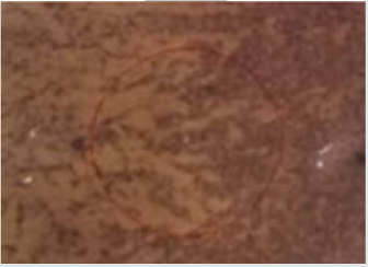
Surface of untreated and treated specimens were examined using a Nikon Epiphot 300 incident light microscope under 100 magnification.

Mechanical tests

Tensile test: Three specimens from each type of untreated, H2O2 and HNO3 surface treated samples were used for tensile test. The test was performed in accordance with the ASTM E8 / E8M - 16a Standard using an Instron servo hydraulic machine 8516. The maximum load, maximum strength and modulus of elasticity were calculated for each specimen.

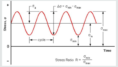
Fatigue Test: Five specimens from each of untreated, H2O2and HNO3 surface treated samples were used for fatigue test using an Instron servo hydraulic machine 8516. A sine curve fatigue cyclic (Figure 1) load was applied for the test. The mean load of the fatigue cycle for all test specimens was maintained at 25 kN which is approximately 80% of the average tensile maximum load that was measured from untreated specimens. The frequency and stress amplitude of the cycle were maintained at 10 Hz and 5 kN, respectively for all tests. The number of cycle and time taken for the failure of each specimen were recorded.

Figure 1: Typical sine curve load cycle for fatigue test.

Lupinepublishers-openaccess-material-science-journal

Results and Discussion

Micrographs of specimen surface

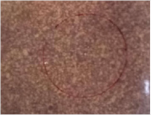
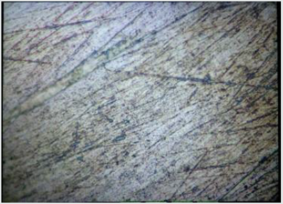
Figure 2: Microscopic image of the surface of a reference (untreated or unpolished) sample at x100

Lupinepublishers-openaccess-material-science-journal

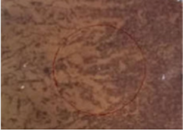
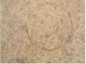
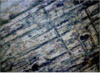
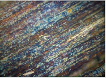
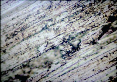
Mechanical polishing provides a smooth surface finish compared to unpolished surfaces. Microscopic image (Figure 2) shows untreated samples had rougher surface with large defects. The surface of polished samples shows apparently smooth surface with very fine scratches as shown in (Figure 3). The H2O2 chemical treatment, referred to chemical passivation method, formed an oxide layer on the surface of the specimens. This treatment is usually conducted to improve corrosion resistance as well as to remove contaminants on the surface of the Titanium alloy. After the hydrogen peroxide treatment, the surface turned into blackish – grey color (Figure 4). It seems a thin film of coating was formed on the surface of the Titanium alloy. The chemical passivation procedure based on nitric acid is used for cleaning and removing contamination, oxides, and small defects. It could dissolve a thin layer of material from the surface and improve the corrosion resistance. Removal of thin layer material could be observed as seen in (Figure 5). The surface defects that existed before the treatment were clearly visible under a microscope as dark patches (Figure 5).

Figure 3: Microscopic image of the polished surface of a sample at x100

Lupinepublishers-openaccess-material-science-journal

Figure 4: Microscopic image of the H2O2 treated surface of sample at x100.

Lupinepublishers-openaccess-material-science-journal

Figure 5: Microscopic image of the HNO3 treated surface of sample at x100.

Lupinepublishers-openaccess-material-science-journal

Tensile property

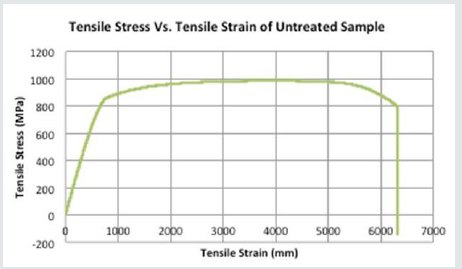
There were no differences in tensile property of untreated and treated specimens observed. A tensile stress-strain graph is shown in (Figure 6) and the tensile test result of treated and untreated specimens is presented in Table 1.

Figure 6: Tensile graph of an untreated specimen.

Lupinepublishers-openaccess-material-science-journal

Table 1: Tensile property Titanium alloy.

Lupinepublishers-openaccess-material-science-journal

Fatigue property

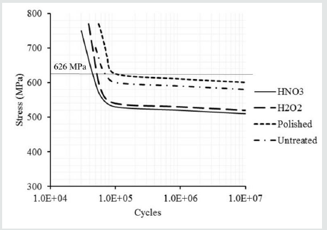
The average number of cycles for failure of untreated, polished, and chemically treated samples are given in Table 2. The fatigue test was designed, and the parameters were set to accelerate the failure for comparative study of different surface treatments.Polished samples had higher number of cycles than untreated and treated samples. H2O2 treated samples took 1,000 more cycles than HNO3treated to fail. However, both chemically treated samples failed earlier than untreated samples. Fatigue failure of a material is usually initiated and propagates from a defect on the surface. When the material is subjected to a cyclic load, cracks at a very small, microscopic scale will begin to form at the stress concentration zone located on the surface of the material [11]. The crack will then propagate and become large with increasing cycle of load and eventually lead to fatigue fracture. The fracture is normally dependent on the size of the defect, and structure of the crack. Untreated (unpolished) samples had surface cracks and failed earlier than compared to polished samples. HNO3 and H2O2treatments that were used for chemical passivation did not improve the fatigue resistance since they neither removed the surface defects nor strengthened the surface.

Figure 7: Comparison of S-N curves of untreated, polished and HNO3 treated Ti6Al4V alloy samples.

Lupinepublishers-openaccess-material-science-journal

Table 2: Number of cycles for failure of different types of samples.

Lupinepublishers-openaccess-material-science-journal

In general, there are two different types of fatigue: high cycle fatigue (HCF) and low cycle fatigue (LCF). HCF is likely to occur at low stress levels and a high number of cycles to failure. LCF occurs at high stress levels and a low number of cycles to failure. Some materials have a fatigue limit or endurance limit that is the stress level below which the material is unlikely to fail.Five different surface treatments such as annealing, shot-peening, ultrasonic shot-peening, deep-rolling, and laser shock-peening were investigated elsewhere for Ti6Al4V alloy [12]. The fatigue test was performed for each type of treated samples and the stress-number of cycle (S-N) curves were discussed [12]. The ultrasonic shot-peened samples had lowest endurance limit 600 MPa than other samples. The highest endurance limit 700 MPa was observed for laser shock-peened treated samples. In this study, the S-N curves were obtained from curve fitting and extrapolating for the untreated, polished, and HNO3and H2O2treated samples. These curves are illustrated in (Figure 7). For the same mean stress of 625.6 MPa, the polished and chemically treated samples failed at low fatigue cycles when compared to shot-peened, ultrasonic shot-peening, deep-rolled, and laser shock-peened samples. As from the comparison the polished specimen was able to endure 105 cycles whereas the shot peened and deep rolled specimens could endure 106 cycles. However, polished samples had the same endurance limit as shot-peened, ultrasonic shot-peened and deep-rolled samples.The fatigue test was performed in an accelerated condition to complete testing of sample in a day. Using a higher amplitude and frequency would have affected the fatigue strength of the specimens. These factors might cause more surface damages during the test and result in rapid initiation of failure. Hence, determining appropriate test parameters is important for such chemically treated samples of Ti6Al4V alloy.

HNO3 and H2O2 passivation treatments could not remove the surface damage or defects. The HNO3 was also etched the grain boundaries of the titanium alloy (Figure 5). Both chemical treatments were unfavorable to fatigue resistance although they have an advantage in chemical passivation. When comparing the number of cycles achieved by the specimens under different surface treatment, it is determined that the mechanically polished Ti6Al4V alloy had a greater number of cycles and had a longer time to reach failure. The Ti6Al4V alloy that gave the chemical treatments distinctly had a reduced time of failure. The micrographs of the specimens also indicated that when the Ti6Al4V alloy was polished, the weak points on the surface were removed. The surface of the Ti6Al4V alloy appeared to be unblemished by application of the HNO3.

Conclusion

The polishing method did improve the fatigue life of the Ti6Al4V Titanium alloy. The chemical passivation method, even though the advantage of the method is to minimize corrosion, the method was unfavorable to fatigue resistance since the number of cycles and time taken for the specimen to break were lower when compared to the untreated specimens. The combination of polishing method and chemical passivation method on the Titanium alloy might help improve the property of the material such as minimize the corrosion factor and at the same time the polishing might increase the fatigue life of the material. Implants used in Brunei Darussalam are mostly treated through the autoclave process. Polishing of the implants could be introduced in Brunei Darussalam so that the fatigue life of implant can be increased by up to 2-3 years more since the common life span of titanium implant can last for around 10-15 years.

Read more about Lupine Publishers Journal of Modern Approaches on Material Science Click on the below link: https://lupine-publishers-material-science.blogspot.com/


Monday, 6 March 2023

Lupine Publishers| What is Quantum Computing and How it Works, Artificial Intelligence Driven by Quantum Computing

  Lupine Publishers| Journal of Material Science


Abstract

Companies such as Intel as a pioneer in chip design for computing are pushing the edge of computing from its present Classical Computing generation to the next generation of Quantum Computing. Along the side of Intel corporation, companies such as IBM, Microsoft, and Google are also playing in this domain. The race is on to build the world’s first meaningful quantum computer-one that can deliver the technology’s long-promised ability to help scientists do things like develop miraculous new materials, encrypt data with near-perfect security and accurately predict how Earth’s climate will change. Such a machine is likely more than a decade away, but IBM, Microsoft, Google, Intel, and other tech heavyweights breathlessly tout each tiny, incremental step along the way. Most of these milestones involve packing more quantum bits, or qubits-the basic unit of information in a quantum computer-onto a processor chip ever. But the path to quantum computing involves far more than wrangling subatomic particles. Such computing capabilities are opening a new area into dealing with the massive sheer volume of structured and unstructured data in the form of Big Data, is an excellent augmentation to Artificial Intelligence (AI) and would allow it to thrive to its next generation of Super Artificial Intelligence (SAI) in the near-term time frame.

Keywords: Quantum Computing and Computer, Classical Computing and Computer, Artificial Intelligence, Machine Learning, Deep Learning, Fuzzy Logic, Resilience System, Forecasting and Related Paradigm, Big Data, Commercial and Urban Demand for Electricity

Introduction

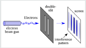
Quantum Computing (QC) is designed and structured around the usage of Quantum Mechanical (QM) concepts and phenomena such as superposition and entanglement to perform computation. Computers that perform quantum computation are known as Quantum Computers[1-5].Note that the superposition from a quantum point of view is a fundamental principle of quantum mechanics. The Quantum Superposition (QS) states that, much like waves in Classical Mechanics (CM) or Classical Physics (CP), any two or more quantum states can be added together (“superposed”), and the result will be another valid quantum state; and conversely, that every quantum state can be represented as a sum of two or more other distinct countries.Mathematically, it refers to a property of solutions to the both Schrödinger Time-Dependent and Time-Independent Wave Equations; since the Schrödinger equation is linear, any linear combination of solutions will also be a solution.An example of a physically observable manifestation of the wave nature of quantum systems is the interference peaks from an electron beam in a double-slit experiment, as illustrated in (Figure 1).The pattern is very similar to the one obtained by the diffraction of classical waves. [6]. Quantum computers are believed to be able to solve some computational issues, such as integer factorization, which underlies RSA encryption [7], significantly faster than classical computers. The study of quantum computing is a subfield of quantum information science.

Figure 1: Double-Slit Experiment Setup.

Lupinepublishers-openaccess-material-science-journal

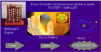
Historically, Classical Computer (CC) technology, as we know them from the past few decades to present, has involved a sequence of changes from one type of physical realization to another, and they have been evolved from main-frame of the old generation to generation of macro-computer. Now, these days, pretty much everyone owns a minicomputer in the form of a laptop, and you find these generations of computers in everyone’s house as part of their household. These mini-computers, Cemeterial Processing Units (CPUs), are based on transistors that are architected around Positive-Negative-Positive (PNP) junction.From gear to relays to valves to transistors to integrated circuits and so on we need automation and consequently augmentation of computer of some sort Today’s advanced lithographic techniques at below sub-micron innovative structure augmenting techniques such as Physical Vapor Deposition (PVD), Chemical Vapor Deposition (CVD), and Chemical Mechanical Polishing (CMP) can create chips with a feature only a fraction of micron wide. Fabricator and manufacturer these chips are pushing them to yield even smaller parts and inevitably reach a point where logic gates are so small that they are made out of only a handful of atoms size, as it is depicted in (Figure 2).

Figure 2: Today’s Chip Fabrication.

Lupinepublishers-openaccess-material-science-journal

It worth mentioning that the size of the chip going way beyond sub-micron technology is limited by the wavelength of the light that is used in the lithographic technique.
On the atomic scale, matter obeys the rules of Quantum Mechanics (QM), which are quite different from Classical Mechanics (CM) or Physics Rules that determine the properties of conventional logic gates. Thus, if computers are to become smaller in the future, new, quantum technology must replace or supplement what we have new as a traditional way of computing.The point is, however, that quantum technology can offer much more than cramming more and more bits onto silicon CPU chip and multiplying the clock-speed of these traditional microprocessors. It can support an entirely new kind of computation with qualitatively new algorithms based on quantum principles! In a nutshell, in Quantum Computing, we deal with Qubits, while in Classical Computing, we deal with bits of information; thus, we need to understand “What Are Qubits?” and how it is defined, which we have presented this matter further down.Next generation of tomorrow’s computer is working based on where “Quantum Bits Compressed for the First Time.” The physicist has now shown how to encode three quantum bits, the kind of data that might be used in this new generation of computer, by just using two photons.Of course, a quantum computer is more than just its processor. These next-generation systems will also need new algorithms, software, interconnects, and several other yet-tobe- invented technologies specifically designed to take advantage of the system’s tremendous processing power-as well as allow the computer’s results to be shared or stored.

Intel introduced a 49-qubit processor code-named “Tangle Lake.” A few years ago, the company created a virtual-testing environment for quantum-computing software; it leverages the powerful “Stampede” supercomputer at The University of Texas at Austin to simulate up to a 42-qubit processor. To understand how to write software for quantum computers, however, they will need to be able to simulate hundreds or even thousands of qubits.Note that: Stampede was one of the most potent and significant supercomputers in the U.S. for open science research. Able to perform nearly ten quadrillion operations per second, Stampede offered opportunities for computational science and technology, ranging from highly parallel algorithms, highthroughput computing, scalable visualization, and next-generation programming languages, as illustrated in (Figure3) here. [8]This Dell PowerEdge cluster equipped with Intel Xeon Phi coprocessors pushed the envelope of computational capabilities, enabling breakthroughs never before imagined. Stampede was funded by the National Science Foundation (NSF) through award ACI-1134872.

Figure 3: Array of Stampede Structure.

Lupinepublishers-openaccess-material-science-journal

Stampede was upgraded in 2016 with additional compute nodes built around the second generation of the Intel Xeon Phi many-core, x86 architecture, known as Knights Landing. The new Xeon Phi’s function as the primary processors in the new system. The upgrade ranked #116 on the June 2016 Top 500 and was the only KNL system on the list.Note that: Knights Landing (KNL) is 2nd Generation of Intel® Xeon Phi™ Processor

What Are Qubits?

A qubit can represent a 0 and 1 at the same time, a uniquely quantum phenomenon known in physics as a superposition. This lets qubits conduct vast numbers of calculations at once, massively increasing computing speed and capacity. But there are different types of qubits, and not all are created equal. In a programmable silicon quantum chip, for example, whether a bit is 1 or a 0 depends on the direction its electron is spinning. Yet all qubits are notoriously fragile, with some requiring temperatures of about 20 millikelvins-250 times colder than deep space-to remain stable. From a physical point of view, a bit is a physical system, which can be prepared in one of the two different states representing two logical values: based on No or Yes, False or True, or simply 0 or 1.Quantum bits, called qubits, are implemented using quantum mechanical two-state systems, as we stated above. These are not confined to their two basic states but can also exist in superposition. This means that the qubit is both in state 0 and state 1, as illustrated in (Figure 4).Any classical register composed of three bits can store in a given moment, only one out of eight different numbers, as illustrated in (Figure 5). A quantum register composed of three qubits can store in a given momentum of time all eight numbers in a quantum superposition, again as illustrated in (Figure5).Once the register is prepared in a superposition of different numbers, one would be able to perform operations on all of them, as demonstrated in (Figure 6)here. Thus, quantum computers can perform many different calculations in parallel. In other words, a system with N qubits can perform 2N calculations at once!

Read More About Lupine Publishers Journal of Material Science Please Click on Below Link:  https://lupine-publishers-material-science.blogspot.com/