Showing posts with label Robotics Journal. Show all posts

Monday, 30 August 2021

Lupine Publishers| Insight Virtual Humanoid Robotics Modeling: the Ultimate Level 0f Artificial Intelligence

 Lupine Publishers| Advances in Robotics & Mechanical Engineering (ARME)


Abstract

I have no doubt to state Virtual Humanoid Robots (VHRs) are the ultimate level of Artificial Intelligence which change the scenario of world and human technologies, it would be applicable in all domains of technology with common factor Ultra Artificial Intelligence (UAI) with disappear and appear ability by any means which boost to our civilization from Type-0 to type-1 civilization at least and would be first step to compete with Aliens technology, if exist (hypothesis only). I would like to define term Virtual Humanoid Robotics (VHR) as “it’s Humanoid Robotics with UAI and has ability to transform from Physical to Virtual by any Internal (Humanoid Self-Control) or External (Human-Control) mode activation mechanism”. VHR is future technology which will use energy from Sun (or Space), Internet of Things (IoT) with RFID USN, Bigdata and Self-learning and healing mechanism. Now I would like to generate future utopia front of your eyes with initial modeling to coined term VHR in this short communication.

Keywords: Humanoid Robotics; Bionic Brain; UAI; Virtual Humanoid Robotics; Robotics Teleportation

Modeling to VHR

a) VHR-Basic Engineering Model

Figure 1:

Lupinepublishers-openaccess-robotics-mechanical-engineering-journal

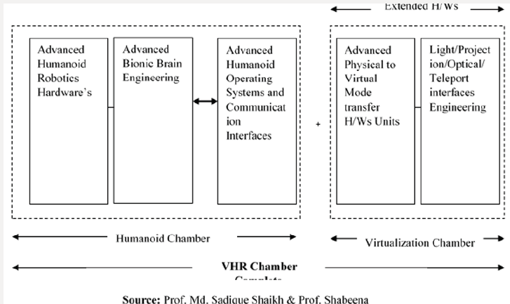
I depicted in my first model “VHR-Basic Engineering” that there we need to extent our fundamental engineering aspect of Humanoid to Virtual Humanoid robotics domain. Hence model divided into two broad chambers as Humanoid Chamber and to give virtual ability Virtualization chamber. As we can analyze from model for successful humanoid building we need advanced Humanoid robotics hardware’s which link to Bionic Brain as similar to human brain mimic in the form of UAI which further cascade to Advanced Humanoid Operating System and Communication Interfaces. After successful engineering of first segment successful physical humanoid can build but to next level i.e. to convert physical humanoid into virtual and back from virtual to physical we doesn’t need to modify hardware but to strongly need to give extension to existed. Hence Virtualization chamber exhibits this regard in model. The virtualization chamber has two functional blocks to engineer Advanced Physical to Virtual Mode transfer Units and Light/Projection/Optical/Teleport interfaces Engineering (Figure 1).

b) Physical-to-Virtual Modes Switch Model

Figure 2:

Lupinepublishers-openaccess-robotics-mechanical-engineering-journal

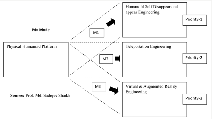
My second purposed model “Physical-to-Virtual Mode Switch” model one of the essential VHR engineering models, in another word can say expansion and detail discussion on Virtualization Chamber second part of my first model. Its lucid and clear representation of concept in model diagram I considered three different possible modes viz. M1, M2 and M3 which may be increase in future with technological advancement and new methods of virtualization. The mode M1 has highest priority to implement VHR where Humanoid hardware itself has ability to appear and disappear itself with selfcontrol (Internal Control) which is only hypothesis right now. The second mode M2 has possible and second priority Teleportation and lot research going on this Mode M2 by several premium university and institutions scholars. The last mode M3 is easiest one but not satisfactory where virtualization engineer using virtual and augmented reality [1-10] (Figure 2).

Conclusion

I have discussed two models and with the help of them try to learn one of the promising and world change future technology “Virtual Humanoid Robotics” where Humanoid not only seems to be like human in near future but also will have ability to Avatar itself. This would be very helpful to send humanoid virtually in deepspace, on stars and planets to understand universe closely with teleportation or internal humanoid mechanism. VHR also ultimate level of AI hence might be shift mankind race on planet earth from Type-0 civilization to Type-1 civilization as shown in sci-fi movies.

Read More About Lupine Publishers Advances in Robotics & Mechanical Engineering (ARME)  Please Click on Below Link: https://robotics-engineering-lupine-journal.blogspot.com/


Monday, 12 July 2021

Lupine Publishers| Forces Acting on A Bearing of an Electric Motor for The Railway Carriage Rounding A Curve

 Lupine Publishers| Advances in Robotics & Mechanical Engineering (ARME)


Abstract

Recent investigations in gyroscope effects have demonstrated that their origin has more complex nature that represented in known publications. On a gyroscope are acting simultaneously and interdependently eight inertial torques around two axes. These torques are generated by the centrifugal, common inertial and Coriolis forces as well as the change in the angular momentum of the masses of the spinning rotor. The action of these forces manifests the inertial resistance and precession torques on any rotating objects. New mathematical models for the inertial torques acting on the spinning rotor demonstrate fundamentally different approaches for solving of gyroscope problems in engineering. This is the very important result because the stubborn tendency in engineering is expressed by the increasing of a velocity of rotating objects. The numerous designs of the movable machines and mechanisms contain spinning components like turbines, rotors, discs and others lead to the proportional increase of the magnitudes of inertial forces that are forming their processes of work. This work considers the inertial torques acting on the on a rotor of an electric railway carriage rounding a curve, which expresses the gyroscopic effects.

Keywords: Gyroscope theory; Inertial torques; Spinning rotor

Nomenclature

i. m - Mass of the rotor

ii. g - Gravity acceleration

iii. I - Index for axis ox or oy

iv. J - Mass moment of inertia of the rotor

v. L - Radius of rolling the carriage along the curvilinear path

vi. R - Radius of the rotor

vii. Tam.i, Tcti, Tcr.i, Tin.i - Torque generated by the change in the angular momentum, centrifugal, Coriolis and common inertial forces respectively, and acting around axis i

vii. Tr.i, Tpi - Resistance and precession torque respectively acting around axis i

ix. ω - Angular velocity of the rotor

x. ω i - Angular velocity of precession around axis i

Introduction

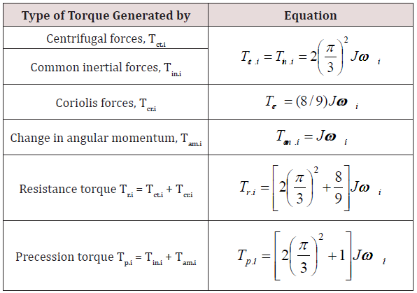
Most of the textbooks of machine dynamics and books that dedicated to gyroscope theory content the typical examples with solving of gyroscope effects [1-3]. However, the practice demonstrates that the known mathematical models for acting forces on the rotating objects do not match their actual forces and motions [4,5]. Recent investigations in the physical principles of gyroscopic motions have presented the new mathematical models of forces acting on a gyroscope [6-8]. The action of the external load on a rotating object generates several inertial resistance and precession torques based on the action of the rotating mass elements of the rotating object. Resistance torque is generated by the action of the centrifugal and Coriolis forces of the rotating object’s mass elements. The precession torque is generated by the action of the common inertial forces of the rotating object’s mass elements and by the change in the angular momentum. These resistance and precession torques act simultaneously and interdependently and strictly perpendicular to each other around their axes. Equations of inertial torques generated by the rotating mass of the rotor are shown in (Table 1) [6].

Table 1: Equations of inertial torques of the spinning rotor.

Lupinepublishers-openaccess-robotics-mechanical-engineering-journal

Table 1 contains the following symbols: J = mR2/2 is the rotor’s mass moment of inertia around the spinning axle; 𝓂 is the mass of the rotor; R is the external radius of the rotor; ωi is the angular velocity of the precession of a spinning rotor around axis i and ω is the angular velocity of a rotor. The following analysis of the actions of several torques and motions around two axes has used the system of subscripts signs. All components of the equations are marked by subscript signs that indicate the axis of action. For example, Tr.x is the resistance torque acting around axis ox, ωy is the angular velocity of precession around axis oy, etc. A different type of the rotating objects as a wheel, discs, etc., possess gyroscopic properties. The electric railway carriage rounding a curve is considered as a flat motion and its electric rotor possess inherent the gyroscopic effects. This work presents the mathematical model for the forces acting on the bearings of the rotor for the electric railway carriage rounding a curve.

Methods

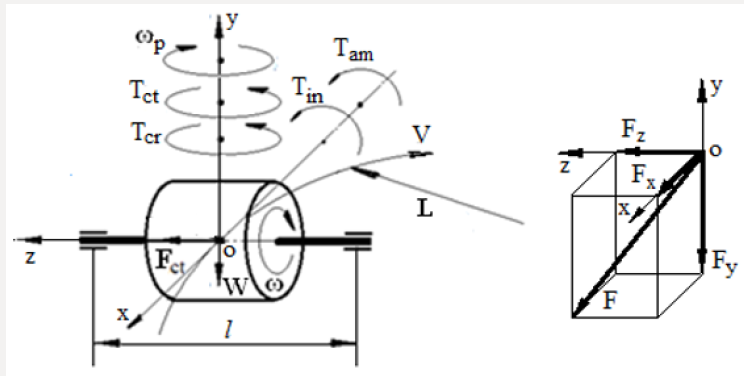
The electric railway carriage rounding a curve and its electric motor is loaded by inertial forces that manifest gyroscopic effects. The curvilinear motion of the of the electric motor demonstrates the gyroscope effects of the spinning rotor, which presented by the action of centrifugal, common inertial, and Coriolis forces and the rate change of the angular momentum. The action of these forces presents the additional load on the bearings of the electric rotor. The study of the action of the inertial forces on the rotor is assumed that electric railway carriage rolls with the constant angular velocity. Figure 1 represents the spinning electric rotor and loads generated by the inertial forces of its mass and weight at the system of coordinate Σoxyz. According to the new mathematical models for the inertial torques acting on the spinning rotor (Table 1), the curvilinear turn of the rotor produces the several torques generated by the rotor’s mass and the weight. The action of these loads produces the reactive forces on the bearings of the rotor’s supports. The inertial torques and other loads acting on the spinning rotor are represented by the following components:

Figure 1: The torques and forces acting on the spinning rotor of the carriage.

Lupinepublishers-openaccess-robotics-mechanical-engineering-journal

a) The resistance torques based on the action of the centrifugal Tctx and Coriolis forces Tcrx acting around axis ox.

b) The precession torques based on the action of the change in the angular momentum Tamx of the rotor and the common inertial forces Tinx acting around axis oy.

c) The curvilinear turn of the rotor on railway generates the centrifugal forces acting bearings of the electric rotor.

d) The weight of the rotor generates the reactive forces on the supports.

Figure 1 demonstrates the action of the inertial torques and the weight on the spinning rotor that moves on curvilinear rail way track. The turn of the rotor around axis oy generates the resistance and precession torques acting around axes ox and oy respectively. These torques are expressed by one equation but with own symbols that represented in (Table 1). The centrifugal force generated by the of the centre-mass of the rotor at the time of the curvilinear motion of the carriage is defined by the following equation:

Lupinepublishers-openaccess-robotics-mechanical-engineering-journal

where Fct.my is the centrifugal force generated by the of the centre-mass of the rotor; 𝓂 is the rotor mass; V is the tangential velocity of the carriage; L is the radius of the carriage rolling on the rail track; ωp is the angular velocity of the carriage on the curvilinear rail track. The rotor’s weight produces the load forces on the rotor’s supports that is defined by the following equation:

Lupinepublishers-openaccess-robotics-mechanical-engineering-journal

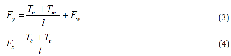
where FWy is the load force generated by the of the centre-mass of the rotor acting on the radial-thrust bearings; W is the rotor’s weight; l is the distance between the bearing and the centre-mass of the rotor; g is the gravity acceleration; other parameters are as specified above. The total forces acting on the bearing of the rotor along axis oy and ox are represented by the following equations:

Lupinepublishers-openaccess-robotics-mechanical-engineering-journal

where Fy and Fx are the total forces acting on the bearing of the rotor along axes oy an ox respectively.

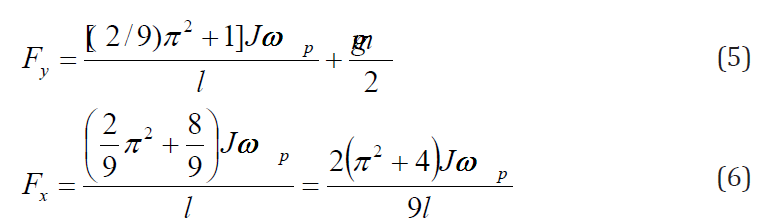
Substituting expressions of the inertial torques generated by the mass of the rotor into Eqs. (3) and (4) and transformation yields the following equations:

Lupinepublishers-openaccess-robotics-mechanical-engineering-journal

The combined load acting on the most loaded bearing of the rotor is defined by the following equation (Figure 1):

Lupinepublishers-openaccess-robotics-mechanical-engineering-journal

where all parameters are as specified above.

The combined load (Eq. (7)) should be used for defining the appropriate radial-thrust bearing of the spinning rotor.

Working Example

An electric carriage is rolling on the curvilinear rail track of radius 300m with the linear velocity of 90.0 km/h. The motor used for traction has a rotor of mass 600kg and the radius of gyration 300mm. The motor shaft is parallel to the axes of the carriage’s running wheels. The rotor is supported in bearings 750mm apart symmetrically and rotates of 160.0 rad/s (Figure 1). Determine the combined force generated by the inertial forces of the rotor and its weight acting on the most loaded bearing.

For solution is defined as the following:

a) The angular velocity of precession:

ωp= V/L= (90000/3600)/300 = 0.083333 rad/s

where V is the linear velocity of the carriage, L is the radius of the rail curve.

b) The rotor’s mass moment of inertia

J = mr2 = 600×0.32 = 54.0 kgm2

where 𝓂 is the rotor’s electric motor mass, r is the radius of gyration.

c) The rotor’s angular velocity

ω = 160.0 rad/s

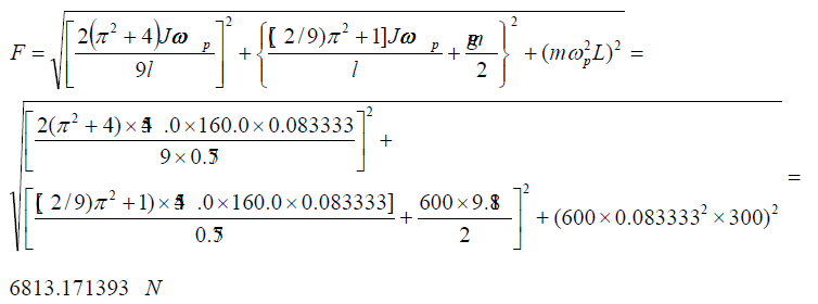
d) The combined force acting on the bearing is defined by the substituting defined above parameters into Eq. (7)

Lupinepublishers-openaccess-robotics-mechanical-engineering-journal

Analysis of obtained result demonstrates that inertial forces acting on the bearing is almost more than two times bigger than the weight of the rotor.

Results and Discussion

New analytical approach to the inertial forces acting on the gyroscopic devices enables developing the equations for the torques and motions of any rotating objects moving in the space. The mathematical model derived for the total force acting on the rotor’s bearing of the electric motor for the carriage rolling on the curvilinear rail track is based on the action of the centrifugal, common inertial and Coriolis forces, as well as the change in the angular momentum and the weight of the rotor. The new analytical approach to the gyroscope problems demonstrates and explains the physical principles of acting forces on a spinning rotor. The mathematical model for the force acting on the bearing of the rotor of electric motor confirms the manifestation of the gyroscopic effects. This model should be used for computing the load on the bearing of the rotor for the movable electric motors and represents a good example for the educational process.

Conclusion

In the area of publications of gyroscopic effects, the forces acting on the rotating objects is one of the most complex and intricate in terms of analytical solutions. The new mathematical models for gyroscopic torques consider the simultaneous and interdependent action of several inertial forces generated by the rotating mass elements and centre mass of the spinning objects. As a practical application, these new physical principles for gyroscopic effects were used for modelling of the forces acting on the spinning rotor of the electric motor. This mathematical model is distinguishing from those in well-known publications, which tend to have complex numerical modelling that does not interpret the origin of gyroscopic effects. The application of new mathematical models for acting forces on the spinning rotor effectively and clearly demonstrates physical principles of loads.

Read More About  Lupine Publishers Advances in Robotics & Mechanical Engineering (ARME) Please Click on Below Link: https://robotics-engineering-lupine-journal.blogspot.com/


Friday, 30 April 2021

Lupine Publishers| How to Become a Manufacturing Cell Fully-Automated Without Robots: Case-Study in the Automotive Components Industry

 Lupine Publishers| Advances in Robotics & Mechanical Engineering (ARME)


Abstract

Productivity is a key factor for companies manufacturing parts and sets to the automotive industry. Automation plays an important role in this matter, allowing development of entire manufacturing cells without the direct need of workers. Even in countries where the labour cost is relatively low, it becomes necessary to improve the level of automation applied to manufacture cells and reduce the dependence of the human labour unpredictability, also increasing the quality and reducing the costs. This case study was developed based on an industrial request in order to improve a semi-automatic cell devoted to seat suspension mat manufacturing. The original cell allows several automatic operations but it needs two workers for two specific operations not considered in the initial design. Thus, new concepts of wire feeding and manipulation were developed in order to allow a better material flow throughout the cell. The new cell was designed and built with success, allowing obtain a fully-automated system, which leads to a better productivity and reliability of the manufacturing process.

Keywords: Fully-Automated Cells; Labour Reduction; Automation Without Robots; Seat Suspension-Mat; Automotive Industry; Mechanical Engineering

Introduction

The competitiveness that is inherent in the automotive industry has and always had a dynamic behaviour. However, there has been, over the last century, the adoption of different strategies, from craft production to mass production of Henry Ford, through the brand policy and the variety of Sloan products, the lean production (lean manufacturing) and more recently to build-to-order initiatives. These changes are not only common to the major producers of vehicles, but were also observed in luxury car producers, seen as artisan producers [1]. The car mass production was a strategy adopted in the automotive industry and started with Henry Ford, founder of “Fordism”, a working model that boiled down to mass produce cars at low cost [2,3]. Today’s consumer wants to influence and participate in the product design, which led to a new paradigm of production strategy. Therefore, at its early stages, the automotive industry had in the market unique models that had a small variety of features, such as the Ford T and Volkswagen Beetle, but in nowadays manufacturing, organizations must be flexible and be able to comprise a long product variety to remain competitive [4]. Indeed, companies must be able to adapt to the market constant changes [5,6].

The value chain related to the automotive industry presents a high degree of complexity [7,8]. A typical supply chain includes car manufacturer (OEM’s–Original Equipment Manufacturers), final components or subassemblies suppliers (Tier 1, 2 and 3), distributors, retailers and customers. The OEM’s are constantly looking for suppliers to whom they can delegate responsibilities in areas such development, sourcing and planning, and this constant search induces pressures in the suppliers to lower prices and make deliveries within the stipulated deadlines, without compromising the products quality assurance. Indeed, quality and delivery time are indicators that highly affect the evaluation of the preferred product supplier [7,9]. In the specific case of the car seat, the evolution from mass to a personalized production, according to customer needs can also be applied. Following the evolution of automobile production, the seat was traditionally produced as an integral part of the automobile, where the available possible configurations were limited or null. With the increasing requirements of customers, this behaviour has changed along the times. With these new realities, the seat became an important element, with different configurations and new component options. The driver can now benefit from a seat with more comfort, extra features or have the possibility of seat heating. Once again, companies must follow the trend of the product variety.

This variety of products can affect the delivery time, which plays an important role in competitiveness. The delivery time can be compromised if a product is standardized or customized, with a shorter time delivery for the first case and longer for the second. Companies thus have the option to choose to reduce the delivery time, engaging in standard products, but companies with customized products must be able to meet the delivery time by means of increased flexibility for customized products [10]. An example to optimize the delivery time was presented in the paint line of the Toyota Motor Manufacturing’s Georgetown plant, where an electronic signal is sent to seat supplier within the information of the customized seat of the car that is present in the assembly line. The seat supplier should manufacture and deliver the seat exactly where it is installed at the Toyota assembly line [11].

A number of industries have been found to be clearly capitalintensive and a number of others clearly labour-intensive [12]. In the last thirty years, many companies located in industrialized countries have been centralized their efforts by upgrading the technological level of their production lines to keep in competition with countries where the production costs are lower, due to low labour costs (non-industrialized countries). This resulted in companies in industrialized countries to migrate from the labour to the capital-intensive model [13]. In some way, a company can be rated in accordance with the amount of capital or labour. If, in one hand, a company with a capital-intensive model has high levels of automation in detriment of hand labour, on the other hand, a labour intensive model usually uses a high amount of hand labour [14].

The automotive industry is not an exception of this classification model and neither of this behaviour. Although the automotive sector involves a high number of hand labour operations [15], and at the same time high automation rates, some companies in less developed countries, is fairly automated and use an intensive hand labour to decrease production costs, although in the industrialized world the manufacturing companies use highly automated and robotized systems. Thus, in general, the automotive sector adopts a capital-intensive model, due to the constant seek for an automated production process. Furthermore, manual assembly lines usually congregate in a complex number of relationships often difficult to study and understand [16,17].

As described before, the customer is an important player in the value chain, and wants his requirements fulfilled. As a consequence, the companies must be in constant changes due to market variations, and to adopt new processes and production technologies using mainly automation [18,19]. Independently of the technologies involved in this process, must of the times companies use automation and robotics systems to increase their competitiveness and productivity, ensuring as well as high levels of quality and repeatability [20]. Automation and robotics, apart from playing an important role in ergonomic problems [21], also help companies to increase productivity and flexibility, despite of some conflicts between these features. Indeed, production and assembly line with high levels of productivity tend to be dedicated and not a flexible system. The automotive industry is endowed with very similar products that can be assembled in the same production line with minor adjustments they adapt their lines. With automation a company is able to reduce the setup time, increase the productivity, improve assembly accuracy, and reduce the human operations [22].

Case Study

Scope

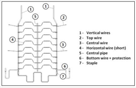
Figure 1: Suspension mat-main components.
Lupinepublishers-openaccess-robotics-mechanical-engineering-journal

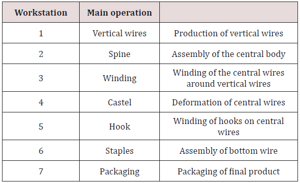
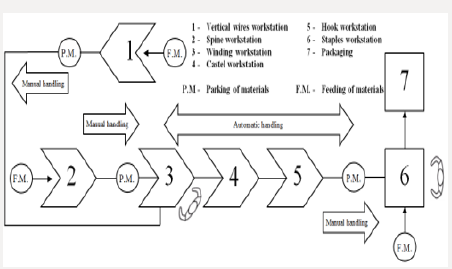
Among various elements that comprise the car configuration, the seat is seen as a key element in the safety and comfort of the driver and remaining passengers. The seat is the element that connects the occupants to the vehicle and plays a key role in security in the event of an accident or sudden manoeuvres, keeping the driver attached to the vehicle frame [23]. This case study was performed on a production line that manufactures a specific component for car seats. The company where the line is installed is dedicated to the production of automobile systems and components. The line is responsible for the manufacturing and assembly of one of several products of the same family, the “Suspension Mat”. Suspension mat is composed by several components obtained by spring steel wire, which vary their geometry and size (Figure 1). Suspension mat support foams either the seat or backrest and is a component that gives the desirable flexibility to the car seat, being as well an element that helps the vibrations absorption from the vehicle structure to the occupants. These features work together aiming to increase the comfort. A brief introduction to the main operations present in the product original process is made in Table 1. Therefore, in order to understand the configuration of the original suspension mat production line, a process layout is presented in Figure 2. A brief overview of process layout is made

Table 1: Main operations of suspension line production line.
Lupinepublishers-openaccess-robotics-mechanical-engineering-journal

Figure 2: Initial process layout of the suspension mat production line.
Lupinepublishers-openaccess-robotics-mechanical-engineering-journal

a) Seven workstations - two of them require human labour to accomplish the final operations (winding and staples workstations), the others five workstations are fully automated.

b) Handling operations - manual handling between several workstations (vertical wires and winding workstation; spine and winding workstation; hook and staples workstation), automatic handling between the winding, castle and hook workstations

Regarding the initial scenario, the suspension mat production line has an inefficient configuration. If, on one hand, the spine and vertical workstation are located in a less favourable area, on the other hand, the cycle time highly varies due to the manual operations (assembly and handling). Apart from this, the layout line configuration is inappropriate to the flow of the suspension mat assembly as well. Although the line has automatic operations, it requires, besides manual handling and assembly between some workstations to complete components, feeding operations of raw materials. Due to these facts, the suspension mat assembly cycle time has an irregular behaviour that affect the process flow. The continuous intervention of manual operations consolidates the assumption: the line is semi-automatic and must be upgraded to a fully automatic line. Indeed, at the original stage, the line has a certain degree of automation that requires a compromise between manual and automatic operations.

The Problem

Companies adopt strategies to raise their production rates while reducing the costs. One of the ways to perform that is to reduce labour costs, especially whose who have repetitive tasks. Unlike the general opinion, cost reduction with employees does not mean the dismissal of the worker, but somehow a growth possibility for the worker, assuming new tasks with higher added-value through adequate formation plans. A lot of advantages are available both for the company and worker.

In order to increase the production rate a strategy for this line migration, which can be defined as semi-automatic, to a fully automated line, was made. At the same time, a zero worker dependency and a standardization of the cycle time should be achieved, in order to reduce the cycle time of product assembly. The implementation of automatic systems where manual intervention exists to complete some tasks is proposed to perform this optimization. Manual feeding of components and the packaging of the final product do not make part of the proposed migration process. To perform the migration process to a fully automated line, it was imperative to execute a survey around the main requirements. As a result of this analysis, several requirements were accounted for. Despite the identification of many detailed requirements, only the main ones were listed:

a) Automatic handling of the vertical wires to the winding station;

b) Automatic handling of the spine to the winding station;

c) Automatic handling of the spine after the previous workstation (hook workstation);

d) Automatic feeding and handling of the lower wire;

e) Final station / Automatic transfer between all stations.

Solutions

To meet all requirements mentioned before, a strategy was defined for the optimization to be possible. As said before, the line is characterized by having two workers that complete the unfinished tasks of the line and, thus, the design strategy focused on the respective stations. Therefore, the optimization process was divided in two different moments: one in the winding workstation, where the first worker is located and at the staples workstation, where the second worker operates.

Phase 1-Winding Workstation

At this station, the worker assembles two components: the vertical wires (vertical workstation) and the central spine (spine workstation). The handling of the two components is also performed by the worker.

Before these two phases and leading to support the manual handling elimination between some workstations, a new layout was set. The spine and vertical wires workstation, which was located outside of the suspension mat assembly process flow is now in a position to improve concepts for handling the components without manual operations.

a) Vertical Wires Automatic Handling to the Winding Station

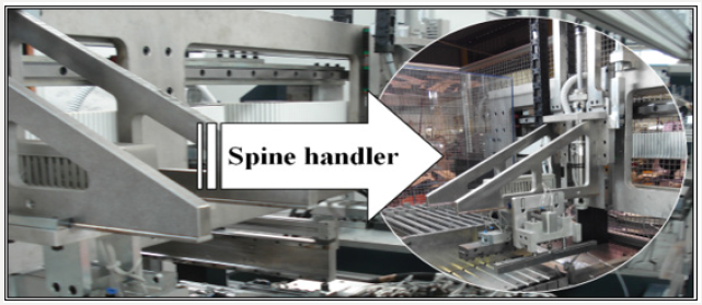
A handler was designed between the spine and the winding workstation, aiming to copy the manual handling movements of the suspension mat spine performed by the worker. Indeed, all systems and concepts idealized in the production line to help the optimization of a fully automated line were applied to replicate the same operations performed by the worker. To proceed with the idealized handler concept, it was necessary a study about the best movement sequence between workstations. Special care has been taken to avoid collisions. If in one hand the handler must fulfil the movement sequence, on the other hand it cannot compromise the workstations operation. To complete the task, the handler was assembled in the existing transfer which, in this stage, transfers the product to one more workstation (Figure 3). It is important to remember that, at the beginning, this transfer only carried out the handling between three workstations.

Figure 3: Spine handler assembled in transfer - handler was implemented in the main transfer in order to simplify the number of movements.
Lupinepublishers-openaccess-robotics-mechanical-engineering-journal

b) Spine Automatic Handling to the Winding Station

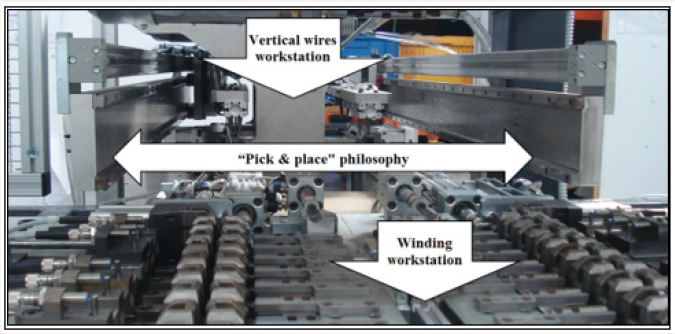
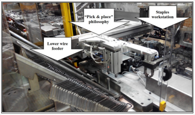
Similar attention in handling the vertical wires to the winding workstation was taken. A simple handling system was considered, which follows a “pick & place” philosophy. This system executes a movement at the same alignment and only has to transport the wire from one location to another. A study was carried out to make the alignment possible and to avoid collisions, aiming to keep the system as simple as possible. Changes in the vertical wires workstation had to be made because the position of the vertical wire is not equal between the two workstations, so this difference could comprise the “pick & place” philosophy. Changes in the workstation and the automatic handling system of the vertical wires were successfully implemented (Figure 4).

Figure 4: Implemented “Pick & place” philosophy - it was possible to develop a compact system to connect two workstations with this philosophy (vertical wires and winding workstations).
Lupinepublishers-openaccess-robotics-mechanical-engineering-journal

Phase 2-Staples Workstation

After the conclusion of the first phase, attention was focused on the second phase. The worker assembles two components in this workstation: the subassembly of the suspension mat arriving from the hook workstation and the lower wire. As in the first phase the manual operations carried out by the worker were studied to complete the migration to a fully automated line.

a) Automatic Handling of the Spine after the Previous Workstation (Hook Workstation)

The communication between the hook and staples workstations was studied in detail. The existing space between the two workstations was eliminated, and an optimized layout was achieved with the removal of this useless area in the line. The staples workstation was moved closer to the hook workstation, and the handling is now made by the main transfer.

b) Automatic Feeding and Handling of the Lower Wire

At this point, the necessary conditions for the automatic feeding and handling of the lower wire were created. The idealized structure to allocate and feed the lower wire to the line allows the continuity of the line as long as possible. The feeding control is assumed by a system that only provides one lower wire when it is requested. To take the lower wire outside of the feeder area, a table was created below the feeder, which creates the proposed conditions, receiving and moving the lower wire with a linear motion, waiting for its removal. To perform the removal and the transport of the lower wire between the feeder and the final position at the workstation, a handler was idealized. Once again, a “pick & place” philosophy was adopted, which is the simplest and fastest solution to perform this operation (Figure 5).

Figure 5: Communication system between workstations - once again “Pick & place” philosophy was adopted.
Lupinepublishers-openaccess-robotics-mechanical-engineering-journal

At the same time, and to complete the implementation of the lower wire feeding, it was necessary to define the best position for the feeder and handler set. As in the vertical wire workstation, the feeding of the lower wire is perpendicular to the process flow of the suspension mat, hereupon the only decision to be made was to move the feeder and handler to the front or to the back of staples workstation. Trying to avoid collisions with a pair of automatic staplers existing in the station, and to keep the system as simple as possible, the feeder and handler set was placed at the front of the workstation.

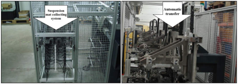
Figure 6: Applied concepts in the final station: a) Suspension mat collecting system at the final workstation; b) Automatic transfer between workstations.
Lupinepublishers-openaccess-robotics-mechanical-engineering-journal

c) Final Station / Automatic Transfer Between All Stations

At the final of the suspension mat assembly, necessary conditions to remove the final set were created. After the staples workstation, a new station was implanted aiming to receive and collect a number of final suspension mat (Figure 6). In order to avoid mechanical or pneumatic support and using only gravity to move the suspension mat, a simple structure was designed. To handle the complete suspension mat to the final station a handler was used as the existing ones in the transfer. The transfer is now able to handle the suspension mat between all workstations. Indeed, the line was successfully migrated to a fully-automated line with the idealized solutions.

Conclusion

The idealized concepts described in the case study have been useful to achieve the proposed goals and helped the complete migration for a fully-automatic line. The proposed solutions were based on careful studies on the worker movements, especially in the handling operations. At the same time, the studies executed before the improvements of the final solutions avoid situations like collisions that could compromise the project implementation. Besides the automation be an area with relative complexity, it was possible to prove that with simple concepts it is possible to solve problems that originally seemed complicated. Indeed, was possible to improve the level of automation and increased the productivity of the line using low cost and simple solutions. The cost/benefit ratio of the solutions is quite important for the final decision. With the replacement of the manual operations by simple and automatic systems, it was possible to transform an inadequate behaviour on the flow process registered in the initial production line scenario in a stable and fluid process, eliminating, among others, possible stops due to lack of materials.

As every automatic migration process, a strategy must be chosen and one of the key points that are questioned is the elimination of the human resources. The elimination of manual stations and the replacement of manual by automatic operations do not imply the dismissal of the worker from the company. Actually, this is an opportunity for both the workers and the company. The worker assumes new functions with higher value and the company benefits by keeping the worker away from repetitive tasks and movements that could be easily replaced by automatic systems. Regarding the new production system now developed, it is expected an increase in the production rate of about 18%, a completely cut of the human labour costs and an increase in the quality level of around 15%. The payback time was estimated in 21 months, i.e., clearly shorter than the expected lifetime expected of the product (about 60 months for this model).

Read More Lupine Publishers Advances in Robotics & Mechanical Engineering (ARME) Click on Below Link https://robotics-engineering-lupine-journal.blogspot.com/


Friday, 12 July 2019

Lupine Publishers - Advances in Robotics & Mechanical Engineering


Abstract


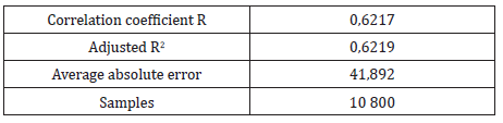
This investigation approaches the artificial neural networks applied to the ore drying process in carbonate-ammonia leaching. To carry out this research, the main variables that characterize the process were identified. Besides, it was collected the data that comprise a whole month of facility´s operation. Furthermore, it was developed a regression analysis backwards, step by step, which allowed to determine that the linear correlation coefficient did not reach values higher than 0,62. In addition, it was pinpointed a two layered feed - forward back propagation neural network to model the temperature. Thins one reached the correlation coefficient values of 0,97 during its training and 0,95 in validation, as well as 0,87 in its generalization.
Keywords: Artificial Neuronal Network; Regression; Feed-Forward Backpropagation; Mineral Drying

Introduction


In a global context, nowadays, modern control systems play a fundamental role when developing solutions to issues or problems presented in domestic and industrial applications. The main contributions of modern control systems at industrial level contribute to technological innovation, profitability and maintainability of the controlled processes. Within the advanced control strategies under investigation to automate complex processes are: adaptive control, predictive control based on models, robust control, and intelligent control, among others. Intelligent control relies on several techniques such as: fuzzy logic, evolutionary algorithms, and artificial neural networks. Artificial neural networks can be used effectively and accurately for modeling systems with complex dynamics, especially for nonlinear processes that vary over time. The growing interest in neural networks is due to its great versatility and the continuous advance in network training algorithms and hardware [1-4]. The nickel producing companies have continuous processes of great complexity that require automation to achieve a greater efficiency in their productions. In the process of ore preparation, it is important to maintain a temperature control at the outlet of the dryer evacuation chamber, in order to obtain the mineral drying with an established humidity level of 4 to 5,5 %. It must also be ensured that the temperature at the outlet of the electrofilters is above the dew point temperature; to prevent the deterioration of electrofilters, which leads to high economic losses, from accelerating considerably. The inefficiencies in the control of the outlet temperature of the dryer evacuation chamber in the ore preparation process are taken as a research problem and as an objective to obtain an artificial neural model for the outlet temperature on the basis of the main input variables, using Matlab as a calculation tool.

Materials and Methods


Description of the Mineral Drying Process

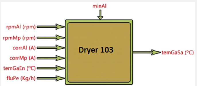
The drying of the ore is carried out in elongated cylinders formed by a combustion chamber where the hot gases that dry the ore are produced, and by the cylinder where the ore will receive the drying process. These drums (Figure 1) have in their interior lifting elements that are responsible for allowing the transfer of heat between the hot gas and the mineral, in addition the dryer drum has a motor system coupled to the body of this which allows it to rotate on its axis. The dryer drum externally rests on two wheels that has two pairs of roller. Internally the dryer is formed near the combustion chamber by guides or baffles welded to the body of the drum that are the ones that direct the mineral towards the outside of the cylindrical part of the drum [5]. The mineral dryer is a complex physical-mathematical modeling object with a large number of input and output parameters which are in a complex interdependence (Figure 2).
Figure 1: Schematic diagram of the dryer.
Lupinepublishers-openaccess-robotics-mechanical-engineering-journal
Figure 2: Structural diagram of the mineral drying process.
Lupinepublishers-openaccess-robotics-mechanical-engineering-journal
The Input Parameters in the Process are:
a) rpmAl - Feed motor speed [rpm].
b) rpmMp - Speed of the main motor [rpm].
c) corrAl - Feed motor power [A].
d) corrMp - Power of the main motor [A].
e) temGaEn -Temperature in incoming gases [ºC] (coming from the Reduction Furnaces Plant).
f) fluPe - Oil flow at the burner inlet [kg/h].
The Output Parameter is:
a) temGaSa - Oulet gas temperature [ºC].
In addition to the input and output parameters, it is important to highlight a specific disturbance of this process that influences it, which is: minAl - Mineral fed to the dryer. It is known that there are other parameters that are involved in the drying process of the ore and that in turn influence the temperature of the exhaust gases in the evacuation chamber (granulometry in the entrance mineral, humidity of the entrance mineral, exact amount of mineral fed to the dryer), but due to the process itself, they are not registered. Due to the automation existing in the process, the values of the process parameters are sensed by the instrument corresponding to each of them and the signal is sent to the computer located in the process control office. The data obtained along 1 month of operation, were recorded every 240s and processed with the Stat graphics Plus V 5.1 software.

Artificial Neural Networks

The determination of the type of artificial neural network, the number of layers and the number of neurons in each layer that best characterize the process of ore drying process was carried out through a trial and error process that plays with the number of neurons and the maximum permissible error. Through Matlab’s Toolbox (nnstart), the performance of artificial neural models was evaluated by using the mean square error and the correlation coefficient between the real values and those obtained by the network [6]. The objective was to provide the network with an adequate number of neurons in the hidden layer to learn about the characteristics of the possible relationships between the sample data. Through the trial and error process, it was identified the feedforward back propagation structure that provided better results. The proposed network consists of two layers: a hidden layer and an output layer. The output layer will only have one unit, which will indicate the value of the oulet gas temperature associated with each input vector presented to the network. The hidden layer will have a variable number of neurons.

Results and Discussion


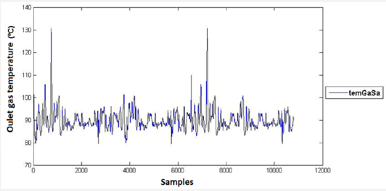
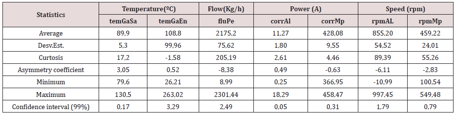
Figure 3 shows the behavior of the exhaust gas temperature in the evacuation chamber, between its minimum and maximum values of 79,59 and 130,51°C, respectively, for the month of work. Once the database was analyzed, the sample functions that evaluate the measures of central tendency and dispersion of the sample were determined through a descriptive statistical analysis (Table 1). The mathematical model that best represents the relationship between the variables analyzed. Table 2 shows the regression analysis for the output pulp density, where a 0,7correlation coefficient is observed.
Figure 3: Control chart for the dependent variable.
Lupinepublishers-openaccess-robotics-mechanical-engineering-journal
Table 1: Summary of the sample´s descriptive statistical analysis for one month.
Lupinepublishers-openaccess-robotics-mechanical-engineering-journal
Table 2: Regression analysis summary.
Lupinepublishers-openaccess-robotics-mechanical-engineering-journal
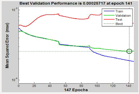
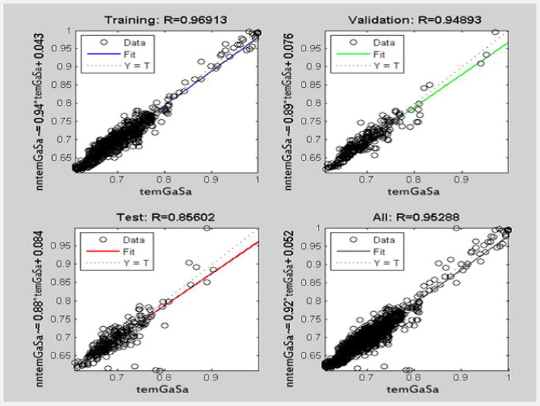
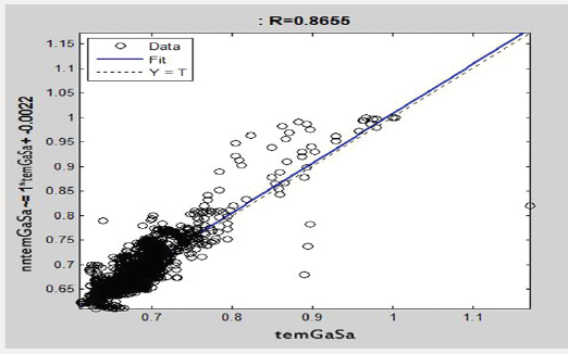
Figure 4 shows the training behavior of the network for the learning process, observing the training, validation and test curves, which converge to the iterations for an error of 0,00026. Figure 5 shows the behavior of the correlation coefficients for the training, validation, testing and adjustment of the artificial neuron network (it is assumed as an artificial neuronal model for the oulet gas temperature in the ore drying process “nntemGaSa” and the real temperature “temGaSa”). Figure 6 shows the generalization of the network with 1767 data not presented during training, where a 0,87correlation coefficient is observed.
Figure 4: Behavior of training and validation of the neural network.
Lupinepublishers-openaccess-robotics-mechanical-engineering-journal
Figure 5: Correlation coefficients of the neural network.
Lupinepublishers-openaccess-robotics-mechanical-engineering-journal
Figure 6: Network Generalization.
Lupinepublishers-openaccess-robotics-mechanical-engineering-journal

Conclusion


The capacity of the feed-forward back propagation network for the simulation of pulp sedimentation processes in the industry was demonstrated. The structure that best characterizes the behavior of the temperature in the exhaust gases of the evacuation chamber is characterized by two layers with 50 neurons in the hidden layer and one in the output layer, with the Levenberg Marquart learning method (trainlm), and the log-sigmoidal (logsig) and sigmoidal hyperbolic tangent (tansig).

For more Lupine Publishers Open Access Journals Please visit our website:

Thursday, 11 July 2019

Lupine Publishers- Advances in Robotics & Mechanical Engineering

Insight Looks to Soft (Continuum) Robotics Advances in Robotics & Mechanical Engineering in Lupine Publishers
Soft Robotics is emerging fresh sub field in Robotics which is very useful in medical, industry, space exploration, deep sea exploration, Nano-robotics and many more likewise applications. The major benefit of Soft Robots as compare to Rigid Robots their excellent flexibility and adaptability to accomplish task. Before to move further I would like to state Soft or Continuum Robots first “Soft Robots are small, medium and big shapes various biological or non-biological body forms robots which are made up using ultra soft and flexible materials, where materials are engineered using Continuum Mechanics and Kinematics. 


For more Lupine Publishers Open Access Journals Please visit our website

Thursday, 27 June 2019

Forces Acting on A Bearing of an Electric Motor for The Railway Carriage Rounding A Curve (ARME)-Lupine Publishers

 
Forces Acting on A Bearing of an Electric Motor for The Railway Carriage Rounding A Curve by Ryspek Usubamatov in ARME in Lupine Publishers


Recent  investigations  in  gyroscope  effects  have  demonstrated  that  their  origin  has  more  complex  nature  that  represented  in  known publications. On a gyroscope are acting simultaneously and interdependently eight inertial torques around two axes. These torques are generated by the centrifugal, common inertial and Coriolis forces as well as the change in the angular momentum of  the masses of the spinning rotor. The action of these forces manifests the inertial resistance and precession torques on any rotating objects.  New  mathematical  models  for  the  inertial  torques  acting  on  the  spinning  rotor  demonstrate  fundamentally  different  approaches for solving of gyroscope problems in engineering. This is the very important result because the stubborn tendency in engineering  is  expressed  by  the  increasing  of  a  velocity  of  rotating  objects.  The  numerous  designs  of  the  movable  machines  and  mechanisms contain spinning components like turbines, rotors, discs and others lead to the proportional increase of the magnitudes of inertial forces that are forming their processes of work. This work considers the inertial torques acting on the on a rotor of an electric railway carriage rounding a curve, which expresses the gyroscopic effects.

https://lupinepublishers.com/robotics-mechanical-engineering-journal/fulltext/forces-acting-on-a-bearing-of-an-electric-motor-for-the-railway-carriage-rounding-a-curve.ID.000104.php


For more Lupine Publishers Open Access Journals Please visit our website


Thursday, 20 June 2019

How to Become a Manufacturing Cell Fully-Automated Without Robots: Case-Study in the Automotive Components Industry

Productivity  is  a  key  factor  for  companies  manufacturing  parts  and  sets  to  the  automotive  industry.  Automation  plays  an  important  role  in  this  matter,  allowing  development  of  entire  manufacturing  cells  without  the  direct  need  of  workers.  Even  in  countries where the labour cost is relatively low, it becomes necessary to improve the level of automation applied to manufacture
cells  and  reduce  the  dependence  of  the  human  labour  unpredictability,  also  increasing  the  quality  and  reducing  the  costs.  This  case  study  was  developed  based  on  an  industrial  request  in  order  to  improve  a  semi-automatic  cell  devoted  to  seat  suspension  mat manufacturing. The original cell allows several automatic operations but it needs two workers for two specific operations not considered  in  the  initial  design.  Thus,  new  concepts  of  wire  feeding  and  manipulation  were  developed  in  order  to  allow  a  better  material flow throughout the cell. The new cell was designed and built with success, allowing obtain a fully-automated system, which leads to a better productivity and reliability of the manufacturing process.


Tuesday, 12 March 2019

Robotics Engineering - #ARME- #Lupine Publishers


The problem of using Blockchain technology in multi-level robotic systems is considered. The management of the robotic systems faces significant difficulties in transferring large amounts of information, securities, metadata, and intellectual contracts. The blockchain technology, based on a decentralized system of distributed registries, allows solving data transfer problems quickly and safely. New digital blockchain-based queuing systems can be effectively used in multi-level control tasks.
For more Lupine Publishers Open Access Journals Please visit our website
For more automation engineering articles Please Click 

Monday, 11 March 2019

Robotics & Automation Engineering Journal- #ARME-#Lupinepublishers


I was started my research only with one thinking “How we feel and understand sadness or happiness of others, why our eyes sometime filled with tears, when we see others crying or sad, why we cheer up when we see others happy, why we bless others, why we care for others, why we become sad when we watch sad seen in movies, why we motivate when we watch something exciting and meaningful in movies, why, why and why?” these are the big questions front of us. My common answer which support to all these questions is “when situation is common between two or more than two people they completely understand each other, because their brains neurons handling same situation. Some time may be feelings for other because of past common situation of us is the present situation of someone or may be some time we think if that situation on me what I would do. Hence common situation either good or bad doesn’t matter but common situation people show strong feelings about each other with respecting emotions and feelings of each other’s and this is because “common situation setup brain-to-brain link between people through which they understand feelings and emotions of each other [1].

For more Lupine Publishers Open Access Journals Please visit our website
For more mechanical engineering journals impact factor  articles Please Click 

Friday, 8 March 2019

Automation Engineering Articles-#ARME-#Lupine Publishers


One of the prominent applications of robots is in assistive therapy using humanoids. Robots are now playing a vital role in our lives as assistants, therapist, companions and much more. Autism Spectrum Disorder (ASD) affects the communication skills and social cues of a person considerably. Recently efforts have been made in the development of communicational, behavioral, motor movements, joint attention and physical behavior of the children suffering from ASD using the humanoid robots. The therapies based on interactive interventions using robots for ASD have proved to be a favorable tool for improving the behavior of children with ASD. There are different ways to identify and improve the behavior in ASD child e.g. psychologists’ sessions, computer vision based bio markers like joint attention measurement and gait analysis, and robot assisted therapies using Autism Observation Scale for Infants (AOSI). In particular the area of robotics is helping a lot in the treatment of ASD as the robot acts as a mediator as well as measures the response of an autistic child.

For more Lupine Publishers Open Access Journals Please visit our website
For more robotics journals impact factor  articles Please Click