Showing posts with label Open access civil engineering Journals. Show all posts

Monday, 18 July 2022

Lupine Publishers| Structural Insulated Panels: State-of-the-Art

 Lupine Publishers| Journal of Civil Engineering and its Architecture


Abstract

This article aims to review and illuminate the latest research conducted on structural insulated panels (SIP) together with the latest information of the current experiment carried out by the authors. The authors attempt to weight up both sides of argument regarding the design methods of SIP: affordability and applicability in construction industry, by taking up-to-date concrete technology and manufacture into consideration. The article primarily shines a light on the new material used for SIP’s skin and core. The fiber-carbon-reinforced polymer plate, glass-fibre reinforced magnesia cement boards, E-glass/polypropylene and glassfibre- reinforced polymer grid have recently been proposed for SIP components material. Besides, the performance of SIPs against wind load is investigated. Far little attention has been paid to SIP connections is in recent research. Economically, there is a need to innovatively alter an affordable material for SIP components to set the scene for its mass production.

Keywords: Structural Insulated Panel; Composite Structure; FRP

Introduction

The modular and prefabricated houses are becoming more popular as today’s customers prefer fast-constructed building in favor of time-consuming processed conventional building [1]. Consequently, due to the demand for prefabricated elements of building the need for structural insulated panels (SIPs) has been highlighted in recent years. Being lightweight, thermal performance and speed of installation are the main advantages of SIP which attracted the researchers’ attention. SIPs can serve the building as both wall and floor. Since emergence of SIP design, in 1930, proposed by the Forest Products Laboratory in U.S., there have been issues regarding its components material, connections, shear connectors and fire resistance [1]. Among aforementioned issues, the propose of an alternative material has attracted researchers’ attention nowadays [1-7]. The conventional material used for SIP skin are sheet metal, oriented strand board (OSB), plywood, cement board. Fibre-reinforced polymer (FRP) plate has been proposed as SIP skin, and also as shear connectors between the two skins of SIP [7-8]. Besides, glass-fibre reinforced magnesia cement board and E-glass/polypropylene laminate have been recently proposed to alter traditional SIP skin material [9-10]. The use of carbon-fibrereinforced polymer (CFRP) sheet for strengthening of SIP skins against lateral loads is becoming popular. Wood wool and cement board are used as SIP skin while expanded polystyrene (EPS) is used as SIP core in this experiment.

Excluding the scale reduction of specimens, the process of SIP assemblage in factory is simulated in this experiment. SIP as an external wall must be resistance enough against wind load. The dynamic response of SIPs subjected to windborne debris impact was examined and came to a conclusion that penetration resistance capacity of SIP is governed by toughness and flexibility of skin material [8]. The SIPs made of EPS core and metal skins was experimentally tested against windborne debris and theoretically evaluated using numerical models developed using LS-DYNA, an advanced general-purpose multiphasic simulation software package, to simulate their dynamic behavior [8]. As a general construction material standard, SIP shall be certified regarding the fire test as it is one of the significant stage of building products commercialization. The full-scaled natural fire tests on the buildings made of SIPs concluded that the SIPs using OSB and EPS met the requirements performance criterion based on UK building regulation [11]. By and large, this article provides the state-of-the art of SIP in order to set the stage for further research to enhance the SIP design. Looking from the economic view, the afore mentioned proposed SIP designs might not be able to compete with those of traditional designs. There is still a need for alteration of affordable material for SIP components, particularly SIP skin. Moreover, the future proposed SIP designs should be simple in order to set the scene for mass production and commercialization purposes.

The state-of-the art

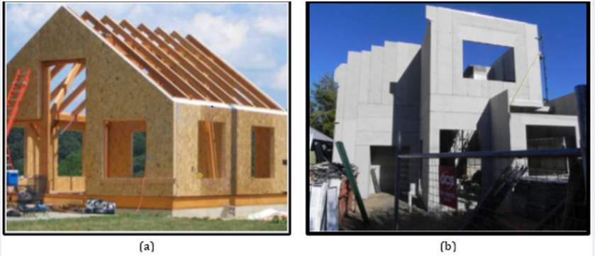
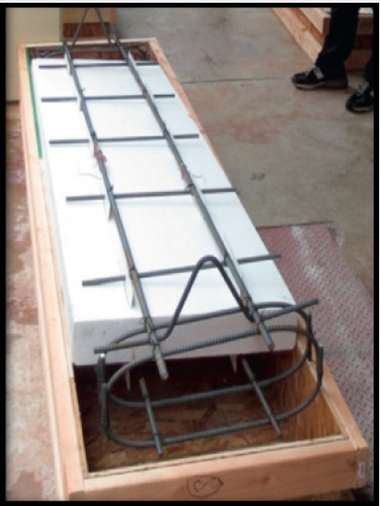
SIPs are special type of precast sandwich panels. These composite building elements are composed of a thick layer of insulating core which is tightened between two thin layers of structural board. The use of SIP dates back to 1930, when the idea of stress skinned panels for building proposed by Forest Products Laboratory in the U.S. This idea has been improving by proposing methods of configuration and installation of SIP as well as proposing alternative material for its skin and core. Sheet metal, oriented strand board, plywood and cement board have been commonly utilised as SIP skin material while expanded polystyrene, extruded polystyrene and polyurethane have been utilised as its core. Figure 1 illustrates two houses made of SIPs. The use of FRP has been rapidly increasing in construction industry particularly for repair and strengthening structural concrete elements [12,13]. A SIP using FRP plates as shear connectors, as shown in Figure 2, was proposed and was analysed by finite element modeling. The shear connectors in design of SIPs has always been an issue as the core of SIP made of soft material may not resist against the shear loads. The three forms of discrete, segmental and continuous connectors were utilised in this study. The proposed SIPs made of EPS foam, FRP plate connectors and ordinary concrete were tested under four-point bending load configuration to evaluate bending failure [8]. However, the design of SIP in this research may not be able to compete with conventional SIP regarding the overall cost.

Figure 1: (a) SIP house with OSB skin [8]; (b) SIP house with fiber cement skin [8].
Lupinepublishers-openaccess-journals-Civil-engineering-Architechture

Figure 2: Cage, installation and shear connectors of proposed SIP [8].
Lupinepublishers-openaccess-journals-Civil-engineering-Architechture

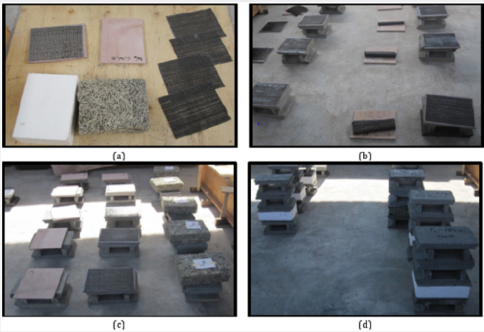
FRP plates were recently put forward to confine top and sides of SIP in a research. The method of dry bond between concrete and FRP plates was adopted in favor of wet bond. FRP plates could act as water barriers which gave more weight to the proposed design of SIP. Overall, the bending tests on scaled and full scale proposed SIPs concluded their better performance compared to traditional solid sandwich panels [6]. The authors of this review article, have recently started a research investigation on SIPs to alter the conventional material of its skin for strengthening purposes. The use of carbon fibre-reinforced polymer (CFRP) sheets, in one, two and three layers, in the interface of the skin and the core, with wet bond, is under an experimental evaluation for buckling behavior of SIP under lateral load to increase its lateral resistance. The skin is made of wood wool and cement board while the core is made of EPS in this experiment. The CFRP-strengthened skins are tightened with core, by applying epoxy and placing the assembled SIPs under uniformly vertical compression using concrete blocks. Figure 3. illustrates the material used and also compression method in this experiment. The primary objective of the experiment is the strengthening of SIPs regarding its application as load-bearing wall. This research emphasises on the lateral loads imposed by wind, in high-rise building where SIPs are used as external walls. Recently, the resistance capacity of SIPs against high speed localized impact caused by windborne debris has been considered in another research.

Figure 3: (a) Cement board, wood wool, CFRP sheet and EPS; (b) cement board skin strengthened with CFRP sheet; (c) strengthened skins and wood wool before assembling SIPs; (d) SIP under uniform compression using concrete blocks.
Lupinepublishers-openaccess-journals-Civil-engineering-Architechture

The dynamic response of SIPs made of EPS and OSB subjected to windborne debris impact was evaluated regarding the penetration resistance capacity. The length of penetration was a key factor in this study. It concluded that the penetration resistance capacity of SIP is governed by toughness and flexibility of skin material [8]. The SIPs made of EPS core and metal skins were experimentally tested against windborne debris and theoretically evaluated using numerical models developed using LS-DYNA, an advanced generalpurpose multiphasic simulation software package, to simulate their dynamic behavior [14]. Apart from FRP material, the use of glassfibre reinforced magnesia cement boards has been proposed by researchers for the skin of SIP. The strength, deformability, failure mode, impact resistance and gradient temperature of full scale SIP panels using this material were experimentally evaluated. The finite element modeling results were in good agreement with findings of research. The research concluded that the proposed SIPs overcome deficiencies of traditional SIPs [10].

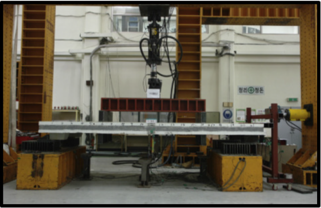
In 2013, the E-glass/ polypropylene laminate was proposed for SIP skin in order to overcome the deficiency of poor impact resistance of traditional SIP skin made of OSB. This research emphasised on retaining all energy-saving benefits of the traditional SIPs [9]. Regarding construction design for seismic loading, the effect of cyclic loading on the composite behavior of SIPs made of EPS foam and glass-fibre-reinforced polymer (GFRP) grid as shear connector was evaluated as the test set up is shown in Figure 4.

Figure 4: Test set up for SIP using GFRP as shear connector [3].
Lupinepublishers-openaccess-journals-Civil-engineering-Architechture

The specimens with similar configurations, were tested under cyclic and monotonic loading. The results showed a lower performance of SIP under cyclic loading than monotonic loading. This was due to the cumulative fatigue loading which damaged the GFRP strands and debonded the interface between concrete and insulation [13]. Moreover, the dynamic modeling of structural concrete insulated panels have been theoretically proved, using finite element modeling, to suit for the design of energy efficient building in seismic area in a comprehensive study. In addition, this study has concluded that, the SIP using polystyrene foam, as insulating core material, was found as the superior to other wall systems regarding sound proofing as well as heating and cooling insulation [2].

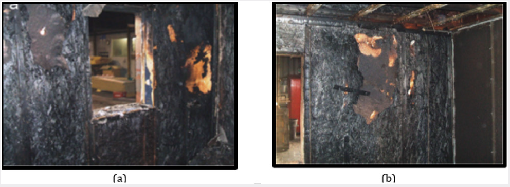
Figure 5: Different view of SIP-made building after fire test [11].
Lupinepublishers-openaccess-journals-Civil-engineering-Architechture

Above all, the fire resistance of SIPs has always been a concern among researchers. A full-scaled natural fire test, which can rarely be found among experimental tests due to its high cost, was recently conducted on four two-storey buildings made of SIPs as illustrated in Figure 5. The SIPs made of OSB and Expanded polystyrene (EPS) were used for two buildings while OSB and Polyurethane (PUR) were used for the other two. The fire test was conducted using softwood timber cribs, with 30 and 60-min durations. It was concluded that theproposed SIPs met the requirements, proposed in document B, based on UK building regulation. Despite the significant deflection of floor, exceeding span/20, no collapse was observed for floors. In addition, there was no collapse or considerable deflection of wall in this test. The researchers attempted to identify the fire spread mechanism in the experimental building, via parameters effective in fire spreading [11].

Conclusion

This article provide the state-of-the art of SIP to set the stage for further research on improvement of SIP design. It has gone some ways towards enhancing our understanding of SIP design. The review has shown that among the current issues on the design of SIP, the use of new and affordable material for SIP skin is needed. In recent years, there has been no attention to the issue of SIP connections together and to other building elements. This issue is essentially needed to be investigated in further research as poor fitment of SIP connections reduces the insulation of entire building. Looking from economic view, the recent proposed SIP designs might not be able to compete with conventional wall and floor designs. There is still a need to alter affordable material in the design of SIP. Moreover, the proposed SIP designs are complicated and not suitable for mass production. Further research shall propose simple design of SIP to facilitate mass production and attain commercialisation purposes.

Read More About Lupine Publishers Journal of Civil Engineering and its Architecture Please Click on below Link: https://lupinepublishers-civilengineering.blogspot.com

Tuesday, 22 February 2022

Lupine Publishers| The Role of Engineering Design in the Infection Control for Hospitals

 Lupine Publishers| Journal of Civil Engineering and its Architecture


Abstract

Hospital buildings are designed with intrinsic features for infection control, and are related to an intensive energy use. The infection control program is structured in a hierarchy of administrative, engineering and PPE controls. Building design plays a major role, because it must not only incorporate the systems that are responsible for infection's engineering controls, but also the features demanded by the administrative controls. Basic understanding of the infection control hierarchy and strategies and stringent communication with the HICC in the design phase is necessary, not only to provide a healthy and safe environment, but to achieve rational solutions that minimize the complexity, operational and maintenance costs. This review paper contributes with basic information about these topics, and presents references for detailed and advanced information.

Keywords: Infection control; Hospital; Healthcare; Engineering design; Ventilation

Abbrevations: ACH: Air Changes Per Hour; ASHRAE: American Society of Heating, Refrigerating and Air-Conditioning Engineers; CDC: Centers for Disease Control; DHHS: U.S. Department of Health and Human Services; HEPA: High Efficiency Particulate Air; HICC: Hospital's Infection Control Committee; HVAC: Heating, Ventilation and Air-Conditioning; MERV: Minimum Efficiency Reporting Value; PPE: Personal Protective Equipment; UVGI: Ultraviolet Germicidal Irradiation; WHO: World Health Organization

Introduction

Hospital buildings are designed with intrinsic features for infection control, which contribute to produce an intensive energy use and significant greenhouse gas emissions [1]. The scope of this review paper is to provide basic information on these intrinsic features, and relevant reference for advanced information.

The Infection control program

In order for an infection to occur, it is necessary the presence of the infectious agent and its source, the mode of transmission, and a susceptible host, in what is called the "infection chain" [2]. The bacterial agents are one of the most common pathogens related to hospital-acquired-infections (nosocomial infections) in the United States [3], but fungal and viral agents are also reported [3]. One of the main sources of these agents, in the hospital application, are the diseased patients. In this case, those pathogens use body fluid secretions, blood, feces and droplets expelled by the respiratory track, among others, as a portal of exit. The expelled droplets are produced in a broad range of sizes during the respiration, talking, coughing and sneezing processes [4]. The larger droplets (order ≥100 μm) settle down within a small distance from the source (1 to 2m), due to the gravitational action. The smaller ones (order < 100μm) may reach sizes that allow them to be suspended for a long time. References [5] and [6] provide detailed information about droplets dynamics in indoor environmental air.

The modes of transmission include direct contact during patient manipulation, indirect contact with contaminated surfaces (fomites) and airborne propagation (also a mode of indirect contact) [2]. Infection by the larger droplets is generally treated as direct contact [2]. Airborne propagation is related to droplet nuclei (size order ≤10μm) [7,8]. Reference [9] provides detailed information about airborne disease transmission.

The infection control program uses administrative, engineering and personal protective control measures [10], in the components of the "infection chain", in order to reduce the infection risk. Administrative controls are based on the stringent application of protocols. These require, among others, that universal precautions (hand hygiene, gloves when touching blood and secretions, etc.), must be used on all patient's manipulation, for instance. Surface disinfection and patient care products sterilization is another administrative control, among others. References [11] and [12] provide detailed information about the infection control program.

Engineering design and infection control

Building design must not only incorporate the systems that are responsible for infection's engineering controls, but also the features demanded by the administrative controls. The design team must keep in mind that engineering controls will not overcome the lacks in administrative controls, but these can promote protocols that can simplify the engineering design. Communication is a key factor for improving the engineering design.

Space design: Layout design must be planned in stringent relationship with the hospital’s infection control committee (HICC), geared to provide adequate patient, staff, materials and waste flows, in order to prevent cross contamination. Basic knowledge on droplet dynamics may be used to understand the infection control criteria that are used to size the gap between patient beds, geared to reduce the risk of cross infection by droplet direct contact. For the case of airborne transmission, the infection control program generally demands that patients with airborne communicable diseases (e.g. tuberculosis, measles, etc.) must be isolated in an airborne infection isolation room (AII) [11]. A Protective Environment room (PE) is generally demanded for the isolation of immunocompromised patients (e.g. bone marrow transplant, oncology, etc.) [11]. Basic knowledge on transmission modes may be used to understand the criteria that is used to request smooth and cleanable finishing for walls and floors, geared to meet the sanitization demands that reduce the risk of cross infection by indirect contact.

Ventilation for dilution control: Although dilution ventilation is a key factor in healthy indoor environments, the design team must be aware that the strategy of increasing ventilation rates, in mixing ventilation mode, has limited effectiveness on airborne infection control [13-16]. Moreover, using high ventilation rates, in air-conditioned spaces, increase energy consumption and may disturb humidity control in hot & humid climates, leading to undesirable mold growth and amplification [17]. Memarzadeh [9] provides an excellent literature review on the role of ventilation on airborne infection control. The reader shall address references [18] and [19] for design guidelines of HVAC systems for hospital applications. Examination of all these studies [13-16] and references [9,18,19] show that maximum rational ventilation rates for dilution control in mechanical ventilated spaces are in the order of 10 ACH. Administrative controls, like source isolation or elimination are more effective than the use of increased ventilation rates, for the prevention of airborne communicable diseases in the hospital setting. The isolation of a source patient in an AII room (single bed) is an example of an administrative control. Staff training for prompt triage of undiagnosed or unsuspected patients with symptoms suggestive of an airborne communicable disease in patient's waiting area is another example. Those patients may be asked to use a surgical mask and instructed to observe strict respiratory hygiene and cough etiquette procedures, while in general public area. Reference [20] provides additional information on administrative control measures for airborne communicable diseases. The WHO [21] provides a guide on natural ventilation for infection control in health-care settings, and this strategy may be an attractive solution for many design locations, notably the low- income developing countries. Reference [10] provides additional information on strategies for reducing healthcare building's energy use, while maintaining or improving effective airborne infection control.

Air filtering and disinfection: Guidelines demand the application of air filters in air-conditioned hospital settings [18,19]. These guidelines recommend that MERV-7 filters (efficiency > 90%, arrestance test) is the minimum filter requirement for coarse particulate control in any HVAC hospital application [18,22]. The requirement of additional filter banks, with higher efficiency for the fine mode particulate control, depends on the application, and is recommended for several ones, in the hospital setting [18,19]. ASHRAE recommends that MERV-15 filters shall be used in all area for inpatient care [18]. This recommendation needs to be analysed by the infection control point of view because of this filter’s high efficiency against the droplet nuclei size order and fine particles size order (size particle most likely to be deposited deep in the lung). Besides that, HEPA filters are often required for some applications, as AII and PE rooms, orthopedic and transplant surgery [18], among others. References [22] and [23] provide detailed information about air contaminants, particulate control and air filter ratings and testing. In the absence of local code requirements, references [18] and [19] provide guidelines on filter selection for air-conditioned hospital applications. However, the room particle concentration decay due to the filtering technique obeys the dilution equation. In this case, the precedent section discussion applies, about the limited efficiency of dilution on infection control. Moreover, the design team must be aware that the application of high-efficiency filters increases the energy use, due to enhanced fan power to overcome the higher pressure loss. In that case, refer to reference [24], for special design considerations that may reduce pressure drop, and provide a rational solution.

An attractive air disinfection technology for airborne infection control is the use of upper-room UVGI (ultraviolet germicidal irradiation) fixtures. This technique relies on the germicidal action of UV in the wavelength range of 200-270 nanometers [18]. The lamp fixture is designed to irradiate the upper-room (unoccupied) zone, while preventing direct irradiation of the occupied zone. An additional room air mixing system (natural or mechanical) is demanded to provide the transport of airborne particles from the occupied to the irradiation zone. References [25-28] provide studies and results on this technique, and references [29-31] provide detailed information on guidelines for installation.

Conclusion

Engineering design plays a major role in the infection control for hospitals. Besides providing the engineering controls, the hospital design must meet the requirements of administrative controls. Basic understanding of the infection control hierarchy and strategies and stringent communication with the HICC in the design phase is necessary, not only to provide a healthy and safe environment, but also to achieve rational solutions that minimize the complexity, operational and maintenance costs.

Read More About Lupine Publishers Journal of Civil Engineering and its Architecture Please Click on Below Link: https://lupinepublishers-civilengineering.blogspot.com


Sunday, 19 December 2021

Lupine Publishers| Stabilization of Expansive Soil Using Wheat Husk Ash and Granulated Blast Furnace Slag

 Lupine Publishers| Journal of Civil Engineering and its Architecture


Abstract

The Expansive soil swells when it comes in contact with water and shrinks on drying. These soils are characterized by inherent swelling and shrinkage characteristics due to presence of Montmorillonite clay mineral, which exhibits volume change behavior under changes of moisture content. Granulated blast furnace slag(GBS) is the waste material which is generated from the steel plant after with the increase in waste disposal problems and their solutions has increased to a where the waste disposal by several methods has become a technology of its own. To minimize the impact of wastes on the environment, final disposal which offers environmentally sustainable methodology for disposing wastes on land is inevitable, after thorough analysis of behavior of soils. Hence, an attempt has been made in the investigation to overcome the disposal problems of GBS that are mixed with wheat husk ash to achieve the desired requirements. In the same way the Expansive soils are treated with different percentage of GBS and wheat husk ash to improve the engineering properties of soil.

Introduction

Expansive soils, well-known as Black Cotton Soils in India, occupy about one-fifth of land area of the country. Black Cotton Soils are residual deposits formed from basalt or trap rocks. Expansive soil contain significant amount of montmorillonite material. These soils are very hard in dry state but lose their load carrying capacity when once they are comes in contact with water. They have high shrinkage and swelling characteristics. In general, these expansive soils are very much keen to changes in environment. The environment includes the stress system, the chemistry of pore water in the system, the seasonal variations in ground water table with consequent changes in natural moisture content and temperature variations. These swelling and shrinkage properties have made the soil unsuitable for civil engineering purposes either as foundation or embankment material.

The compaction is a mechanical process in which the densification is achieved through the expulsion of air voids at almost constant water content of the soil mass. However, densification through consolidation is primarily attributed to the gradual expulsion of pore water from the voids of the soil mass undergoing consolidation and to the increase in the effective stress on the soil mass. Stabilizing agents such as fly ash, quarry dust and rice husk ash are used for the stabilization of expansive soils. In the same way GBS is one of the materials used as stabilizing agent [1-5].

Soil properties that influence shrink-swell potential: The influence of shrink-swell potential depends on the following factors:

    a. Clay Mineralogy: Clay minerals which cause soil volume changes are montmorillonite, vermiculites and some mixed layer minerals. Illites and kaolinites are infrequently expansive, but can cause volume changes when particle sizes are extremely fine.

    b. Dry Density: Higher densities indicate closer particle spacing, which may greater repulsive forces between particles and larger swelling potential.

    c. Plasticity: In general, soils that exhibit plastic behavior wide ranges of moisture content and that have high liquid limits have greater potential for swelling and shrinking. Plasticity is an indicator of swell potential.

Soil water chemistry: swelling is depressed by increased cat ion concentration and increased cat ion valence.

Ground water: Shallow water tables provide a source of moisture and fluctuating water tables contribute to moisture.

Permeability: Soils with higher permeability, particularly due to fissures and cracks in the field soil mass, allow faster migration of water and promote faster rates of swell.

Temperature: increasing temperatures cause moisture to diffuse to cooler areas beneath pavements and buildings.

Laboratory tests used for identification of expansive soils

In Engineering practice, the common identification schemes are based on standard classification results, such as grain size analysis and Atterberg's limits. However, other tests such as microscopic examination, X-Ray diffraction and differential thermal analysis for identifying the type and amount of minerals used in identifying potentially swelling soils (Table 1.1).

Table 1.1: Laboratory tests used in identification of Expansive soils.

Lupinepublishers-openaccess-journals-Civil-engineering-Architechture

Physical properties of expansive soils

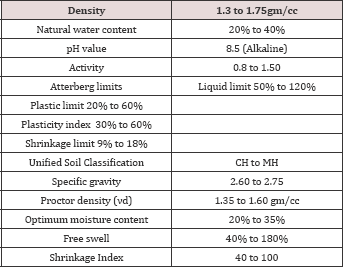
The typical characteristics of Expansive soil are shown in Table1.2

Table 1.2: Physical properties of expansive soils (Anand, KS 1989).

Lupinepublishers-openaccess-journals-Civil-engineering-Architechture

Methods of stabilization

The stabilization techniques may be grouped under the following two major heads

    A. Stabilization without additives

    B. Stabilization with additives

Stabilization without additive may be mechanical rearrangement of particles through compaction or addition or removal of soil particles [6,7]. Some of the stabilization process can be studied as follows:

Chemical stabilization

Besides the use of lime, other chemicals both organic and inorganic can be used to stabilize the expansive soils. But the cost of cement stabilization is considerably more than that of lime stabilization. GBS is added to the soil-lime mixture to increase pozzolanic reaction. Chemical like potassium, deactivation of sulphates with calcium chloride, water proofing with silicones or asphalts, cementation with silicates, carbonates all proved in reduction of plasticity index.

Wheat husk ash

India wheat husk ash for stabilization appears to be successful solution, wheat husk ash is readily available. Primarily being siliceous material act as pozzolona. Hence in this investigation the compressibility behaviour of black cotton soil treated with GBS and wheat husk ash has been studied. Wheat husk ash is obtained by burning locally available wheat husk in an open kiln for about twenty four hours. After complete burning, the burnt material was sieved through I.S.425 micron sieve and minus 425 -fraction was taken for the study.

Materials used

For the present study, Expansive soil, GBS and wheat husk ash have been used. Their physical properties have been determined.

Expansive soil

In India, 20% of surface deposits are covered with expansive soils. The Expansive soil swells when it comes in contact with water and shrinks on drying. These soils are characterized by inherent swelling and shrinkage characteristics due to presence of Montmorillonite clay mineral, which exhibits volume change behaviour under changes of moisture content. Due to characterized swelling and shrinkage behaviour of expansive soils leads to the severe damages to the Civil Engineering structures such as cracking in buildings or total distractions of the structure, foundations and pavements. For the present investigation the Expansive soil was obtained from Rudnoor village, Bhalki taluka, Bidar district, Karnataka state, India. It is collected from an open excavation at a depth of 0.5m below the natural ground surface. The soil was air dried and pulverized. This pulverized soil passed through 425 micron IS sieve has been used for this investigation.

Granulated blast furnace slag

Granulated blast furnace slag (GBS) was obtained from Kirloskar steel plant district Koppal, Karnataka, India. GBS is the waste material which is generated from the steel plant after with the increase in waste disposal problems and their solutions has increased to a where the waste disposal by several methods has become a technology of its own. To minimize the impact of wastes on the environment, final disposal which offers environmentally sustainable methodology for disposing wastes on land is inevitable, after thorough analysis of behaviour of soils [8-9].

Wheat husk ash

Wheat husk ash is obtained from Byalahalli village, Bhalki taluka, Bidar district in Karnataka state in India by burning locally available wheat husk in an open kiln for about twenty four hours. After complete burning, the burnt material was sieved through I.S.425 micron sieve and minus 425 -fraction was taken for the study.

Results and Discussion

The liquid limit, plastic limit, shrinkage limit and compaction tests were conducted based on the experimental programme. The effect of additives on index and compaction properties of expansive soil treated with various percentages of GBS and WHA have been studied. The results and discussions are presented in the following section (Table 1.3).

Read More About Lupine Publishers Journal of Civil Engineering and Architecture Please Click on Below Link: https://lupinepublishers-civilengineering.blogspot.com

Monday, 20 September 2021

Lupine Publishers| Electron Beam Additive Manufacturing with Wire

 Lupine Publishers| Journal of Civil Engineering and Architecture


Introduction

   Electron beam additive manufacturing with wire (EBAMW) is a novel technology which can directly fabricate 3-D near-net shape elements from metal wires. Of specific interest are the additive layer manufacturing processes with wires that are capable for producing fully dense metallic and hybrid parts in which the resulting parts may be used for loaded structure. This process is attractive because it eliminates contamination compare to powder process. Manufacturing near-net-shape elements layer-by-layer with wire as a deposit material offers a great potential for time and cost savings in comparison to conventional manufacturing technologies (such as casting, forging, etc.). The increasing market especially for aerospace industry demands for titanium, aluminum and other materials serial production parts has promoted wire- feed processes in recent years, as repeatability, material properties, material usage, possible part size, and building speed have also become issues.

Research carried out up to date was focused on the possibility of using EBAMW in space [1,2] and the ability to produce ready-made elements that meet the requirements of the space sector industry. Mitzner et al. [3] revealed that through the use of modulation of electron beam the refinement of the microstructure in the titanium alloy can be achieved. Gonzales et. al. [4] indicated that the use of flux cored wires containing aluminum, iron and boron allows manufacturing Ti-6Al-4V titanium alloys with a more stable and finer microstructure. The rapid prototyping process using a beam allows to produce a Ti-6Al-4V titanium airframe element at lower cost compared to older solution. The reduction of material consumption by 79% was achieved. The aim of the presented work was to carried out research on electron beam additive manufacturing with a stainless steel wire as a filler material. The scope of the work was to investigate the influence of selected EBAMW technological parameters such on stability of deposition process.

Methodology

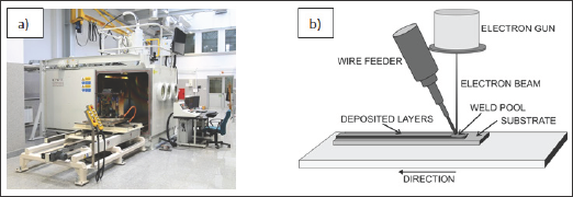
The EBAMW process was conducted based on EB machine CVE XW150 model: 30/756 (Figure 1). The device is equipped with a wire feeder and a working chamber with a volume of 4.9m3. The device is equipped with a system to monitor and record of the process parameters. The following parameters were applied during experimental tests: feeding angle 30°, working pressure 5•10-5mbar, beam current in the range of 1-30mA, accelerating voltage from 60 to 150kV, wire feed rate from 600 to 3600 mm/ min, travelling speed from 200 to 7000mm/min. To an additive manufacturing specimens welding wire 1.2mm in diameter (LNM307 Lincoln Electric: C 0.07%, Mn 7.1%, Si 0.8%, Cr 18.6%, Ni 8.0% wt.) was applied.

Figure 1: Electron beam additive manufacturing with wire set up a) EB machine b) scheme of the process.

Lupinepublishers-openaccess-journals-Civil-engineering-Architechture

Results and Discussion

The scope of the work was to investigate the influence of technological parameters such as: wire feed rate, beam current, travelling speed, acceleration voltage on stability of the deposition process and geometric dimensions of the padding welds, single layer as well as whole structure. The research revealed that, at low beam currents, the deposition process is unstable. The padding weld reinforcement is non-uniform. Irregularity of the width, height and straightness of the padding welds can be observed. At too high acceleration voltage and beam current, burn-through of plate and excess penetration weld can be revealed. When the wire feed rate is too high, the amount of energy supplied is insufficient to stabilize the fusion process of the wire. The wire is deeper feeding into the welding pool and limits the possibility of creating of a channel. The increased volume of filler material flooded the channel and caused that the welding pool becomes wider.

The gained knowledge as well as results of preliminary experimental tests including study of influence of technological parameters on with and high of single padding welds allowed to produce the fully dense metallic parts based on electron beam additive manufacturing process with wire. The results are presented in Figure 2. The EBAM 307 steel plate was fabricated in a vacuum chamber. The deposited path was scanned in one direction. It means that the return movements in opposite direction were dead. The spacing between two adjacent tracks (overlap) was 1.3mm. The scanning directions were alternated layer to layer and the time interval is 2 min. Eighteen layers were deposited and average height of each layer was approximately 1.0mm. The following technological parameters were applicable: accelerating voltage U=60kV, beam current 15mA, travelling speed 1000mm/ min, wire feed rate 1000 mm/min, feeding angle 30°. Number of padding welds in one layer was 42 [5].

Read More About Lupine Publishers Journal of Civil Engineering and Architecture Please Click on Below Link https://lupinepublishers-civilengineering.blogspot.com