Lupine Publishers | Journal of Environmental & Soil Sciences
Abstract
The scarcity of conventional energy resources rises in the fuel prices and harmful emissions from the burning of fossil fuels have made power generation from conventional energy sources unsustainable and unviable. It is envisaged that the supply–demand gap will continue to rise exponentially unless it is met by some other means of power generation. Inaccessibility of the grid power to the remote places and the lack of rural electrification have prompted for alternative sources of energy until a developed stage of using renewable energy is mature and economical. Until then, a significant research and development is needed in the field of innovative use of hydrocarbons and energy efficiency, such as:
I. Carbon Capture, Storage and Utilization (CCSU) technologies.
II. Conversion of gas to liquids and chemicals (GTL).
III. Compressed Natural Gas (CNG) and Liquefied Natural Gas (LNG) technologies.
IV. Fuel Cell and Hydrogen (FCH).
V. Intelligent Energy Management (energy storage).
VI. Repowering and retrofitting.
VII. Hybrid Power Generating Systems (fossil and renewable sources).
VIII. Green Refinery Processes and Systems.
Keywords: Carbon Capture; Conversion of Gas to Liquid; CNG and LNG; Fuel Cell and Hydrogen; Energy Storage; Repowering and Retrofitting; Hybrid Power; Green Refinery
Abbreviations: CAES: Compressed Air Energy Storage, CCSU: Carbon Capture, Storage and Utilization, CNG: Compressed Natural Gas, CSP: Concentrated Solar Power, DHC: District Heating and Cooling, FCH: Fuel Cell and Hydrogen, FT: Fischer-Tropsch, GTH: Gas to Hydrate, GTL: Gas to Liquids, HRSG: Heat- recovery steam generators, HRES: Hybrid renewable energy system, ISCCs: Integrated Solar Combined Cycle Power Plants, LNG: Liquefied Natural Gas, NGCC: Natural Gas-Fired Combined Cycle, PFBC: Pressurized fluidized-bed combustor
Introduction
Because of the increase in energy demand and the prospective shortage of the fossil fuel with time, there is increasing in the need of sustainable resources. Hence, this is initially handled by using clean fuels [1], utilization of waste heat [2-6] and adopting different configurations [7,8], where resources and environment are conserved. The power generation from traditional energy sources is unsustainable and unviable because of the lack of traditional energy resources, increasing in the fuel prices and harmful emissions from the burning of fossil fuels. It is expected that this supply–demand gap will continue to increase exponentially unless it is met by some other means of power generation. unavailability of the grid power to the remote places and the scarcity of rural electrification have prompted for alternative sources of energy. The renewable energy resources, like sun, wind, water and biomass, have become better alternatives for conventional energy resources [9]. The important feature of hybrid renewable energy system (HRES) is to combine two or more renewable power generation technologies to make use of their operating characteristics is the best and to get efficiencies higher than that could be obtained from a single power source. Hybrid systems can address limitations in terms of fuel flexibility, efficiency, reliability, emissions and economics [10].
Compared to fossil fuels, renewable energy resources display a strong disadvantage: their interrupted nature. However, concentrated solar power (CSP) is a very important electricity generation technology, compared to other renewable electricity generation systems, because of its ability to incorporate a gas turbine. With a gas turbine technology, a hybrid operation guarantees a dispatch able power. while, conventional gas turbine power plants do not have a real ability for the integration of another intermittent energy source [11-13]. Because of the high decrease of fossil fuel reserves and the international commitment for the reduction of pollutant emissions, alternative energy sources are being intensively sought. Solar energy is one of the candidate energies sources to at least partially substitute fossil fueled generation plants. But, up to now generation costs for producing electric energy from pure thermo-solar input are high compared to conventional production [14]. There is a strong problem related to ensure a constant and predictable power delivery to the grid. One possible alternative are solar-fossil hybrid thermo-solar power plants. Among them, those based on a gas-turbine scheme have additional advantages as reliability, quick start-up and shutdown processes, fully dispatch able power, and probably the most important, very low water consumption. This is especially relevant in high solar irradiance areas usually linked to arid conditions [15].
All those reasons have led during the last years to important efforts to develop prototype and experimental plants to investigate the viability of the hybrid solar gas-turbine plant concept. Solar gas-turbine plants work by use of concentrated solar power to heat pressurized air displaying a Brayton cycle before entering the combustion chamber. The combustion chamber adds the demanded energy to fill the gap between the air temperature after receiving the solar input energy and the turbine inlet temperature. Modern recuperated gas-turbines are thus combined with a solar receiver usually located in a central tower [16]. Integrated Solar Combined Cycle Power Plants (ISCCs), contains a Concentrated Solar Power (CSP) plant and a Natural Gas-Fired Combined Cycle (NGCC) power plant, have been recently introduced in the power generation sector as a technology with the potential to simultaneously reduce fossil fuel usage and the costs of integrating solar power in an electricity system. This study quantifies the economic and environmental advantages of an ISCC power plant relative to a stand-alone CSP with energy storage, and a NGCC plant [17].
Carbon Capture, Storage and Utilization (CCSU) Technologies
CCS needs to be transported to safe geological storage, rather than being emitted to the atmosphere. Commercial deployment of CCS is expected to include cost reductions for CO2 capture technology and improved techniques for monitoring store CO2 . CCS will always require additional energy compared to projects without CCS [18]. Carbon capture and storage (CCS) is currently considered to be technically feasible at commercial scale using a range of technologies. Such as carbon dioxide (CO2 ) injection activities in the oil and gas industry. Electricity generation projects with CCS producing 275 MW or more have been proposed around the world [19]. A number of R&D activities to develop technologies that would contribute to CCS implementation can be identified including:
a. actions to reduce costs.
b. Identification, performance and monitoring of appropriate storage sites [20].
CO2-Capture Technologies
Post-combustion capture:
a. CO2 removed from the combustion products just before they are vented to atmosphere.
b. Wet scrubbing with aqueous amine solutions and regeneration.
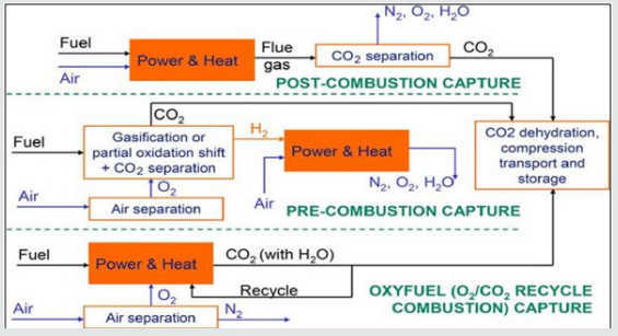
c. The CO2 removed from the solvent in the regeneration process is dried, compressed and transported to safe geological storage [21] (Figure 1).
All types of fossil fuels can be gasified (partially combusted) with sub-stoichiometric amounts of oxygen result in a ‘synthesis gas’ mixture of predominantly CO and H2 . Additional (steam) is then added and the mixture is passed through a series of catalyst beds for the ‘water–gas shift’ reaction to approach equilibrium: CO+ H2 O3 CO2 + H2 (This promotes CO conversion to CO2 ) [22]. The CO2 can be separated to leave a hydrogen-rich fuel gas. The separation process typically uses a physical solvent. Energy requirements for CO2 capture and compression in pre- combustion capture systems may be of the order of half that required post-combustion capture. But pre-combustion capture systems have to pay an efficiency penalty for the shift reaction [23]. Three main lines of CCS technologies with respect to efficiency, energy consumption, and technical feasibility, Figure 2 [24]. More gasification and gas turbine design economics are urgently needed for IGCC to capitalize on its emissions and carbon capture advantages [25]. The utility industry generally perceives IGCC power generation as not yet fully commercially proven. Subsequent CO2 removal is accepted as commercially mature technology. IGCC is 10-20% more expensive [26]. The shift would then be applied to the desulfurized (sweetened) gas bulk CO2 removal. Tradeoffs between sour vs. sweet shift need to be studied for each gasification technology and feedstock [27].
Conversion of Gas to Liquids and Chemicals (GTL)
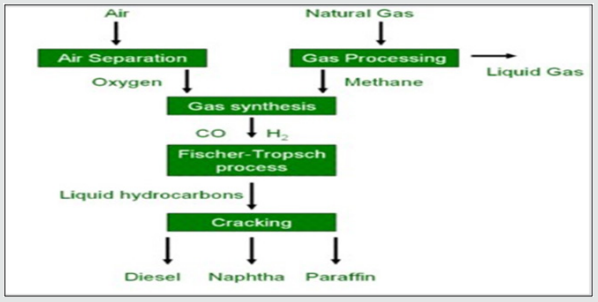
Chemical conversion of a gas containing hydrogen and carbon monoxide into synthetic crude (syncrude) by the Fischer-Tropsch (FT) synthesis process. The syncrude is then refined by traditional methods to produce liquid transport fuels [28]. Gas (H2 , CO) (Using FT)àSynthetic Crude (refined)àliquid transport fuel. As a feedstock, the process uses synthesis gas (syngas) generated from the gasification of solid, liquid or gaseous carbon rich materials, such as coal, natural gas or biomass [29].
Processes GTL process comprises three main steps:
a) Gas treatment: To remove impurities from the syngas and, where necessary, correct the hydrogen to carbon ratio (H2/CO) to within the acceptable range for FT synthesis.
b) FT synthesis: To produce syncrude by catalytic conversion.
c) Product work-up and refining: Separation of gases, hydrocarbon liquids and waxes then refining these into final products [30].
Impurities
A. Some impurities act as a poison to downstream catalytic reactions in the GTL process and reduce the efficiency of the process.
B. These impurities include condensed oils, solid particles, arsenic, mercury, oxygen, compounds of Sulphur and carbon dioxide [31].
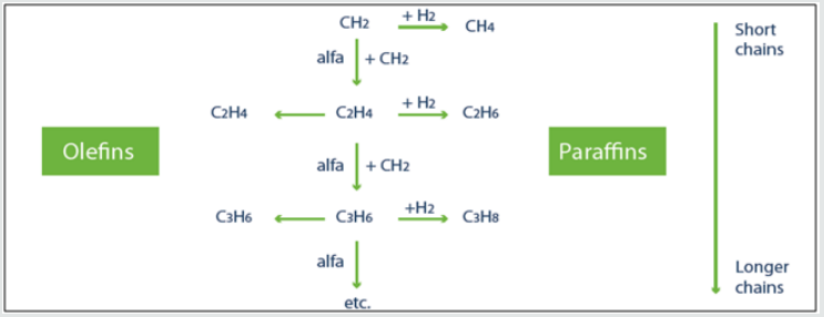
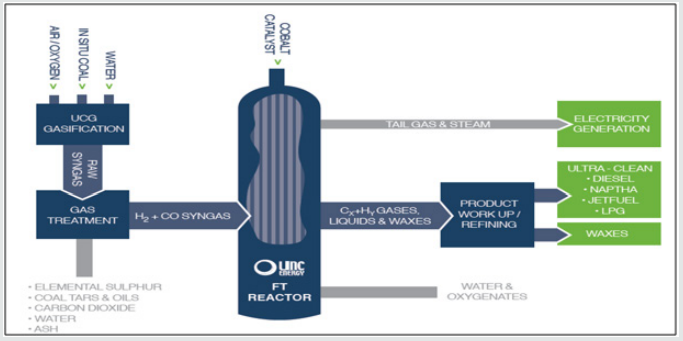
These originate from the coal itself or through its gasification. Removal of contaminants from the gas can be by catalytic conversion or by adsorption or absorption [32]. On completion of gas treatment, the syngas is free of impurities and is rich in H2 and CO, which are the basic elements needed to manufacture syn-crude. Gas treatment in commercial scale plants is undertaken using proprietary processes that are readily available and have a long history of development and operation [33]. A significant advantage of the gas treatment processes considered is that a clean CO2 stream is obtained. The stream of captured CO2 is ready for sequestration should that option be economically feasible. The purpose of FT synthesis is to combine CO and H2 into carbon chains by reacting carbon monoxide and H2 in the presence of a catalyst, heat and pressure. When focusing on diesel fuel production, the preferable carbon chains are long, saturated and paraffinic in nature (linear hydrocarbons containing only single bonds carbon-to carbon or carbon-to-hydrogen) [34]. Both olefins and paraffin’s will adsorb and desorb from the catalyst surface, causing the products to consist of a mixture of paraffin’s (Figure 3). GTL plants are generally significant users of electricity. The power used is for gas compression, heating and cooling. However, there are opportunities to use waste heat and steam recovery options for power generation [34,35] (Figure 4).
Gas to liquids
Thus, gas to liquids (GTL) is a refinery process to convert natural gas or other gaseous hydrocarbons into longer chain hydrocarbons such as gasoline or diesel fuel [36,37] (Figure 5).
Methane to methanol process
Methanol is made from methane (natural gas) in a series of three reactions [38].
Steam reforming
CH4 + H2 O → CO + 3 H2 ΔrH = +206 kJ mol−1
Water shift reaction
CO + H2 O → CO2 + H2 ΔrH = 41 kJ mol−1
Synthesis
2H2 + CO → CH3 OH ΔrH = 92 kJ mol−1
Moreover, making liquid from natural gas could reduce carbon emissions and improve energy security [39].
Compressed Natural Gas (CNG): An Alternative to Liquefied Natural Gas (LNG)
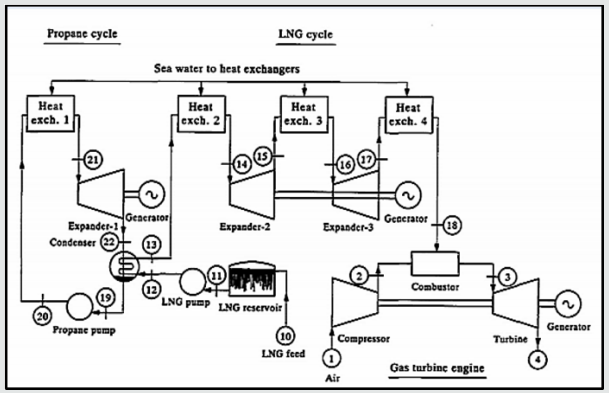
Natural gas is transported to the markets by pipelines as LNG. Transporting the natural gas by pipelines is convenient and economically attractive onshore. For the offshore transport of natural gas, pipe- lines become challenging as the water depth and transporting distance increase. LNG, an effective means of transporting gas for long distances across the seas, constitutes 25% of the world gas movement. But LNG projects need huge investments, along with substantial natural-gas reserves, and are economically applicable for distances of 2,500 miles and beyond [40]. There are a lot of research works have been investigated on combined cycles displaying their proportional advantages such as: high thermal efficiency (47-50%), moderate capital cost, low cooling water requirement, fast loading, high reliability, operational flexibility, and environmental acceptability [41]. As shown in Figure 6, heat is taken from the LNG which is supplied at - 162°C and 53 atm in three stages. The first is through the condenser of a propane Rankine cycle, using sea water as the heat source. Having passed through the condenser, raising the LNG to - 35°C at 50 atm, the LNG is then passed through two expanders to the gas turbine engine, with three sea water heat exchangers being used [42].
The expanders of both circuits drive generators. The waste energy recovered by using the cryogenic plant is expected to improve the power and efficiency of the whole power plant. However, a thermo economic decision must be taken with regard to the feasibility of this combined plant [43]. CNG provides an effective way for shorter-distance transport. The technology is purposed at monetizing offshore reserves that can’t be produced due to the inaccessibility of a pipeline or due to the LNG option is very costly. Technically, CNG is easy to deploy, with lower requirements for facilities and infrastructure [44]. The results show that for distances up to 2,500 miles, natural gas can be transported as CNG at prices ranging from U.S. $0.93 to $2.23 per MMBTU compared to LNG, which can cost anywhere from $1.5 to $2.5 per MMBTU depending on the actual distance. At distances beyond 2,500 miles, the cost of delivering gas as CNG becomes higher than the cost for LNG because of the disparity in the volumes of gas transported [45]. Subsea pipelines, on the other hand, are appropriate for much-shorter-distance natural-gas transportation. The commercial promise for CNG is in shorter distance and smaller volume (and, therefore, smaller required dedicated reserves) for sea-going natural-gas transportation vs. LNG [46].
Converting natural gas to LNG reduces it to one-six-hundredth of its standard-conditions volume, allowing transportation by specialized tanker ships over long distances. The production and storage of LNG are usually conducted in onshore facilities. The major components of the value chain include:
a. natural gas production,
b. the liquefaction process (the “cascade” cycle is the most common technology) in which the pretreated natural gas becomes liquefied at a temperature of approximately (–160°C).
c. transportation.
d. regasification
e. distribution [47].
The equipment involved in the processing and transportation of LNG is very capital intensive and highly specialized. The liquefaction plant is the most expensive unit of LNG production, costing from U.S. $750 million to $1.25 billion. This is nearly 50% of the total investment. Offloading of the LNG requires special facilities, namely a regasification terminal. Regasification facilities cost $500–550 million depending upon terminal capacity. LNG tankers, dedicated specifically to each project, are complex and expensive [48]. Shipping of LNG is a function of distance of transport. Assuming the ships for transporting LNG are newly built, the unit cost of shipping ranges from U.S. $0.41 to $1.5/MMBtu for distances from 500 to 5,000 miles. Overall for LNG, the total investment can range from U.S. $1.5 to $2.5 billion depending on the market needs and number of ships required [49].
Compressed Gas
The gas can be pressured up to 200 atm at ambient temperatures. Another approach to transporting CNG has been named the Votrans (Volume Optimized Transportation and Storage), in which the natural gas is compressed and cooled to lower temperatures. This reduces the volume of the compressed gas, compared to just compressing it at ambient temperatures [50]. At the lower temperatures of -17 to –40°C, the process works at lower pressures than would be required at ambient temperatures. For the Votrans concept, the ships carry the chilled compressed gas in a boxlike structure called the “CNG module”. The design of the module consists of horizontal or vertical stacking of pipes [51].
Gas Compression
The basic concept for CNG is to compress the original natural gas, which is at a certain temperature and pressure, to higher pressures and, in one method, chill it to lower temperatures. Specially designed ships, which have an inclusion system, transport the cold compressed gas. The technology can be divided into three parts: compression, refrigeration, and transportation. The required power by the compressor and compression stage can be calculated on the basis of the compression ratio, volume of gas, temperatures, and pressures [52].
Transportation
The technology part of transportation includes the loading, the voyage using the CNG carriers, and the unloading. The transportation of CNG is capital intensive, requiring 85 to 90% of the total capital requirements for the process. The onshore infrastructure for loading the compressed gas into the ship requires mainly the compressor and accessories. The chillers are on board the transporting ships, which reduced the need for special loading infrastructure to handle chilled fluids. Unloading of the gas is accomplished with a fluid-displacement mechanism. The displacing fluid is a mixture of ethylene glycol and water [53].
Cost of CNG Technology
This transport of natural gas requires less capital to deploy than LNG and is well suited to exploit isolated supply sources and limited consuming markets. A CNG plant with loading facilities including compressors, pipelines, and buoys costs U.S. $30 to $40 million. CNG ships, with chiller and fluid displacement on board, cost from $150 million to $300 million for ship capacities of 400 to 1,000 MMBtu for Veterans. The number of ships required for a certain transport distance depends upon the loading rate, voyage distance, and time required for a ship to make a complete cycle of loading, transporting, unloading, and returning. Therefore, the required CNG ship numbers will increase with the transportationdistance increase [54].
CNG vs. LNG
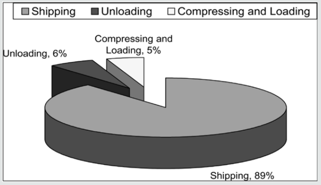
In comparing CNG with LNG, the same transporting-ship realvolumetric capacity is used. However, in making the comparison, it is worth remembering the disparity in the actual standard volume of the gas transported. For the same ship capacity, LNG transports 2.1 Bcf of natural gas compared to a maximum volume of 1.2 Bcf transported as CNG [55]. To compare CNG with LNG, a review of the costs involved with both is indicated. These do not include the transportation costs of ships and other facilities required for loading or unloading. For CNG, the ships cost approximately U.S. $230 million, while for LNG, the ships cost approximately $160 million. The simplicity of the CNG operations provides an added advantage over LNG. The equipment required is easily available, with little or no detail to be customized. Both technologies share the common need for specially built ships carrying the respective cargoes of LNG or CNG. For LNG, the main consideration during its transportation is maintaining the state of the liquid, which in the case of CNG is simply maintaining the pressure and temperature without concern for changes of phase [56] (Figure 7).
H2 and Fuel Cells
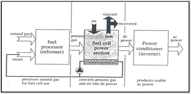
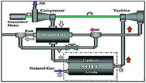
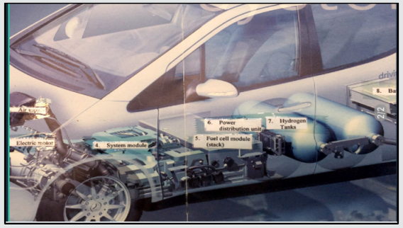
The key criteria for an ideal alternative fuel are inexhaustibility, cleanliness, convenience, and independence from foreign control. H2 is considered as one of the most promising fuels for generalized use in the future. Mainly because it is versatile, energy- efficient, low polluting, and a renewable. Hydrogen is environmentally favorable replacement for gasoline, heating oil, natural gas, and other fuels in both transportation and industrial applications. In nature, mostly the hydrogen is engaged to either oxygen or carbon atoms. So, to get hydrogen from natural compounds, there will be energy expenditure. So, hydrogen is considered as an energy carrier- a means to store and transmit energy derived from a primary energy source [58]. Presently hydrogen is mainly used in production of gasoline, fertilizers and metals. However, hydrogen requires energy to produce, store and distribute. Hence, hydrogen technologies need to be developed to reach the stage of competing with fossil fuels and other alternatives to produce power [59]. These technologies should emphasize efficient systems to reduce energy losses, and emissions. Among high efficiency technologies, fuel cells appear to be the most promising with high efficiency and very low environmental impact. Fuel cells are able to convert the fuel chemical energy into electricity, heat and water by reverse electrolysis, Figure 8. This leads to a much higher conversion efficiency. Both considerable primary energies saving and pollutant reduction, are achieved by upgrading conventional systems to fuel cell hybrid plants, Figures 9 & 10. Oil is essential in the transport sector while natural gas will become a more dominant fuel in power generation. Hydrogen economy is expected to offer considerable opportunities. Fuel cell development is an important step to the efficient use of hydrogen hence, research must continue in this area.
Figure 11 shows an experiment was done in Jordan University of Science and Technology for testing fuel cells and nanotechnology. The preferable solution is producing H2 from sustainable sources: wind energy, solar energy, waterpower or biomass. However, these energies will not be able to provide a massive contribution to meeting the energy demand for many decades to come.
i. Environmental reasons (large scale tolerance of wind energy).
ii. Practical reasons (availability of surfaces).
iii.
Economic reasons (cost of photovoltaic energy).iv. Technological reasons (storage of intermittent energies).
1. Hence, the fuel cell is seen to be the most efficient energy converter in the near future, using H2.
However, it still has major problems, such as:
A. Reducing the cost of fuel cells by a factor of 90%.
B. Enhancing the performance and durability of fuel cell systems by factor of 2.
C. Reducing the H2 production and distribution costs by a factor of 3.
Intelligent Energy Management
Energy Efficiency
Energy efficiency is a convenient technology to be adopted by the developing countries. Energy conservation implies reduction in the consumption of energy, such as (turning thermostats down) [61]. Consuming less energy results in protection of the environment and preventing climate change through forcing people to make sacrifices in comfort, pleasure and convenience. Efficiency implies obtaining more useful heat, or work from each unit of energy supplied, either by technological improvements or reducing waste. Hence, Energy efficiency could be described in three ways:
a) Less energy for the same benefit (conservation).
b) The same energy for a greater benefit.
c) More energy for an even greater benefit.
Only the first description of energy efficiency (conservation) is sustainable. The second doesn’t lower gross energy use, and the third increases it.
If promoting energy efficiency, enhances the benefits of the end users, and doesn’t reduce the impact of energy and environmental costs. This is not sustainable. Improved energy efficiency must lead to measurably less gross energy use (reduced use of fossil fuels) and polluting emissions. Improved “energy efficiency technology” involves much more efficient: motors, air conditioners, furnaces, direct and indirect water heaters and computers [62]. Variable speed drives and variable volume HVAC with direct digital control, and energy management. Cogeneration and air-to-air heat pumps reduce the use of electricity and fuel in commercial buildings. Engines, for transportation, to have lighter aluminum blocks, fuel injection, turbo charging, overhead cams, automatic speed controls, and using unleaded fuel with catalytic converters to reduce emissions [63]. The bodies and frames of the cars to become lighter, smaller and more unified. They are made lighter with plastics and fiberglass shaped into aerodynamic forms. steel belted radial tires, front wheel drive, disk brakes with anti-lock features, light emitting diodes [64]. Interstate highway systems, speed limits legalized, carpooling, and most recently, the internet, email, and telecommuting reduced gasoline consumption and improved energy efficiency.
In power industry
Combined cycles and cogeneration systems. Trigeneration of power, heating and cooling. One-third of the oil used in most countries is used in transportation, by passenger cars and light trucks. The overall fuel efficiency of vehicles could be increased by improvements primarily in aerodynamics, materials, and electronic control [65].
The most fuel-efficient cars are:
a. Compact with small engines, manual transmission, low frontal area, front wheel drive and reduced vehicle weight.
b. Radial tires usually reduce the fuel consumption by 5 to 10 percent by reducing the rolling resistance.
Compressed Air Energy Storage CAES
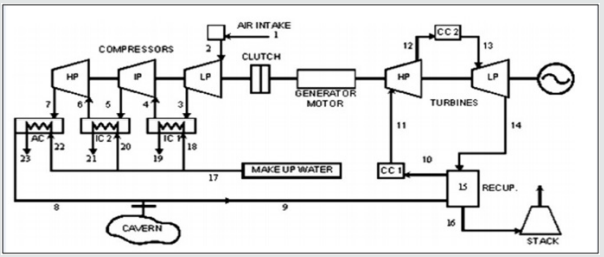
Many countries devise their energy plans based on a preplanned energy mix option. Some do not have hydraulic systems and decided to exclude nuclear energy due to obvious reasons. Solar and wind, although the most mentioned renewable energy as important and clean, they have many drawbacks not the least being costly, intermittency, energy recovery and intensity. They do not constitute a high percentage of the world energy consumption. Hydrogen and fuel cells are nearer to the research and development stage. Some countries have some experience in utilizing gas turbines as a mature technology, with available caverns from oil fields, underground tunnels or especially designed and excavated, in a CAES system [66].
CAES has excellent load shaving characteristics, utilizing excess available energy at night, otherwise engines remain running in a spinning reserve non-efficient mode. Relatively much higher power (about 65%) when desperately needed for industry at a higher efficiency during the day becomes available instead of the nominal power [67]. CAES technology can help in increasing the viability of renewable sources. The integration of a wind farm and a PV system with CAES technology has been analyzed on a daily cycle. Integration of CAES and heat storage enables trigeneration of electrical power, heating and cooling to be produced. CAES has the common advantages of peak load gas turbine power plants and that of the pumped storage scheme [68]. The primary energy efficiency ƞpe, amounts to 47%, which could increase with higher air discharge rates. Thereby, CAES plants enjoy economic superiority at part loads versus the conventional gas turbine engines [69].
Repowering and retrofitting of Fossil Fuel Power Generation
Repowering
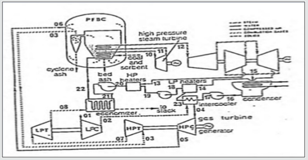
Utilities have been adopting repowering as an option in their plants to meet the growth in loading. Repowering of older and marginally efficient steam plant by conversion to combined-cycle operation is carried out by the addition of a twin-shaft gas-turbine engine and a pressurized fluidized-bed combustor (PFBC). The lowpressure compressor rotates at variable speed to provide the PFBC with the required mass of air satisfy various load conditions [70]. Four arrangements were studied as shown in Figure 12, namely the basic System 1 with a heat exchanger interposed between the gas turbine and the PFBC, in addition to circulating the condensate of the steam plant through the gas turbine intercooler; System 2 circulates direct cold water; System 3 cancels the heat exchanger; System 4 cancels the heat exchanger and raises the turbine inlet temperature to 1250 C to anticipate the future performance of advanced systems. Results show the system 2 achieves marginal improvement, whereas system 3 achieves 7.3% higher power and 4% higher efficiency relative to System 1. System 4. achieves figures of 33.4 and 13.2% respectively [71]. In their continuous planning for load growth, utilities search for the most economic generation, subject to a number of constraints. One of the options open to many utilities with existing steam units is re-powering, which involves the installation of gas turbines and heat- recovery steam generators (HRSG) to convert older and marginally efficient steam plant to combined- cycle operation. One obvious benefit of re-powering relative to new construction is the saving in capital investment, mainly because of the re-use of existing equipment and structures, the use of owned land, existing transmission capacity and the sharing of infrastructure with other units [72].
Other important advantages are lower operation and maintenance costs, accruing from the sharing of existing support facilities and staff, and less complicated relicensing by the use of the station’s thermal discharge permits and intake structure. The combined cycle efficiency that comes of using large modern gas and steam turbo-sets is higher than that of current supercriticalpressure reheat steam power plants [73]. Furthermore, this efficiency is achieved with lower capital investment for standardized gas turbines and matching highly conventional sub-critical pressure steam conditions, and shorter periods for delivery and installation. Generally, the capital investment for such conversions, which improve overall station heat rate and increase station output, can yield high rates of return especially where high fuel costs prevail. If natural gas is available economically, gasturbine re-powering can offer many benefits besides increasing plant output and efficiency. These include lower specific emissions, improved operation and maintenance costs, improved capacity factor for large existing fossil-fuel units, higher reliability and improved operational capabilities such as cycling, load following and peaking [74]. The main disadvantages re-powering includes the complexity that may result when new high-efficiency units are matched to old equipment. There is also a potential for increased maintenance frequency of refurbished equipment. However, the repowering option is believed to be economically competitive overall. The major re-powering methods based on gas-turbines, involving fairly conventional technology and cycle configurations, call for addition of new equipment to an existing boiler/steam turbine installation such as substituting HRSG, adding supplemental HRSG, and gas turbine exhausting into the hot wind-box or feed-water heater. There could also be consideration of station re-powering where generating plant is replaced by a new combined cycle, retaining some existing plant auxiliaries and systems [75] (Figure 13).
Retrofitting
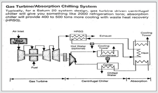
Gas turbines are emerging as a superior economic and environmental alternative to electric and diesel drives for refrigeration chillers- for retrofit and new application. Until recently, many of the facilities have used electric motor driven chillers or, in some cases, reciprocating engines. However, for economic and environmental reasons, there is growing interest in gas turbine drivers and gen-sets for both retrofit and new DHC operations [76]. In general, gas turbines have become serious competitors for refrigeration chiller applications. Key factors in favor of going to natural gas fired gas turbines as a driver for future applications are the high cost and uncertainty of electricity under peak demand conditions. Peak electric demand will only continue to rise in coming years. This raises the possibility of outages that would be less likely to occur in natural gas fueled turbines drive units [77]. There’s also question of cost: in a typical large building requiring 1500 to 2000 tons of refrigeration, the chiller system can account for 50% or more of electric demand and typically cost in range of $14000 to $ 15000 per month. With gas, you can achieve significant saving in fuel prices. Chillers loads are very expensive loads to satisfy with electric power, because they usually occur at a time of day when energy costs are highest. In addition to the fact that gas is less expensive than electricity at peak conditions, the demand for natural gas is lowest in the summer months which is when chiller loads are highest. This means that refrigeration operators can purchase gas at the lowest spot market prices available during the year. For these reasons, we feel you will see more and more DHC plants providing steam in winter months and chiller loads during the summer, Figure 14 [78].
Hybrid Power Generation Systems
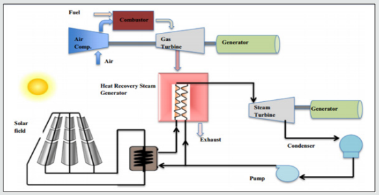
It has become essential for the power and energy engineers to search for the renewable energy sources like wind, sun, geothermal, ocean and biomass as prospective and cost-effective alternatives for traditional energy sources. However, because of these renewable energy resources not available all the time during the year that has led to investigate in the area of hybrid renewable energy systems. In the past few years, a lot of research has taken place in the design, optimization, operation and control of the renewable hybrid energy systems. It is indeed evident that this area is still emerging and vast in scope [79] (Figure 15). The unprecedented increase in the demand for energy and in particularly electricity has led to a huge supply-demand gap in the power sector. The scarcity of conventional energy resources rise in the fuel prices and harmful emissions from the burning of fossil fuels has made power generation from conventional energy sources unsustainable and unviable [80]. It is envisaged that this supply-demand gap will continue to rise exponentially unless it is met by some other means of power generation. Inaccessibility of the grid power to the remote places and the lack of rural electrification have prompted for alternative sources of energy. The renewable energy resources, such as wind, sun, water, sea and biomass, have become better alternatives for conventional energy resources [81].
HRES is becoming popular for stand-alone power generation in isolated sites due to the advances in renewable energy technologies and power electronic converters which are used to convert the unregulated power generated from renewable sources into useful power at the load end. The important feature of HRES is to combine two or more renewable power generation technologies to make best use of their operating characteristics and to obtain efficiencies higher than that could be obtained from a single power source. Hybrid systems can address limitations in terms of fuel flexibility, efficiency, reliability, emissions and economics [82]. Solar PV and wind systems are the primary sources of energy. This energy is available in abundance but is intermittent in nature and site specific. To overcome this drawback, back up energy devices (secondary sources) are introduced into the system to supply the deficit power and to take care of transient load demands. Renewable energy sources essentially have random behavior and cannot have accurate prediction [83]. To provide a trusted and economic supply from the new technologies of renewable energy, need a huge scale, effective cost, efficient energy storage system to keep the lights on when there is no blowing for the wind or no shining for the sun. the needed storage technology is not existing and is unlikely to emerge in the next 20 years [84].
Modern power systems are huge, complex and inherently unstable. If the changes are too much, the lights will go out. The discontinuous energy technologies like wind power and solar power give a new source of main changes and increase the difficulties of keeping the light on [85]. Most power systems have a capacity factor of between 50% and 70%. In some countries the peak demand occurs in winter evenings (heating loads) and in the middle of summer (air-conditioning loads) in other countries. Power systems have a need for “frequency keeping” to guarantee that the amount of generated electricity completely matches the demand. Such as, the beginning and end of a popular TV program [86]. If there is an unexpected loss of a huge amount of generating capacity, then it is occasionally needful to shed part of the load to avoid a system collapse (blackout). Unlike traditional power stations, a change in the output of large wind farms of 50% in short time is not strange. The efforts to expect the output of wind farms more than an hour or so ahead have not been successful [87]. Capacity factors vary from 18% to 37%. At a 25% capacity factor wind power costs about 12c/ kWh at the station gate. In the US, the costs of power generation of coal and nuclear are 2–4c/kWh. A new Finnish study calculated a cost for nuclear of 3.5 Euro cents (5.25 US c) and for coal of 4.5 Euro cents (6.75 US c). The solar power capacity factor is about 20%. The output changes predictably every day and unpredictably every time a cloud passes over the sun and drops the output by as much as 60%. The capital cost is in excess of $5000 per peak kW. The unit cost is around 40cents [88].
Most new renewable energy technologies increase the cost and problems of operating a power system because they are discontinuous and/or unexpected and their output varies quickly. For a power system operator, there is no difference between a large load change and a quick change in the output of a large wind farm or solar power plant. None of these renewable energy technologies would exist without grants, tax breaks and massive subsidies. In addition, consumers, taxpayers and ratepayers, not the generators, pay for the cost of transmission and backup power stations [89]. Modern economies can make a massive reduction in the consumption of energy without any effect on the economy. A lot of these demands come from organizations participated in carbon trading or the already heavily subsidized renewable energy industry. Renewable Energy Council (Europe’s largest renewable energy trading association) said that it was possible to exchange all United States power generation from coal, nuclear and oil-fired power stations with low cost renewable energy. However, most of this renewable energy-wind and some solar and ocean would be discontinuous and migrant [90].
These claims all ignore:
A. The big and complicated problem of storing the energy when it is available so that it can be used when it is needed;
B. The serious problems of coping with the unpredictable and rapidly fluctuating output of the wind farms;
C. The very high real cost of wind power.
D. The cost and problems of the large-scale long-distance power transmission that would be needed [91].
To clarify the problems listed a demand of 10,000 MW with a capacity factor around 60% giving a yearly energy demand of about 55,000 GWh pa. was studied the total cost of supplying this system, from:
a) The well proven combination of nuclear power and hydro pumped storage.
b) A combination of wind power and pumped storage [92].
Nuclear power is not well suited to following variations in load it is normal practice to associate nuclear power stations with hydro pumped storage. This allows the nuclear power stations to run efficiently and economically at a steady output. The pumped storage schemes pump water into an upper reservoir when the load is low and uses this water to generate extra electricity when the load is high. For a nuclear-based system these pumped storage schemes need to have sufficient storage for about 10 hours’ operation at maximum output. lines would be heavily utilized. Assuming a typical wind power capacity factor of 25% and allowing for pumping losses, the system supplied by wind power needed 31,000MW of wind power to generate the required 68,000 GWh pa. It is well established from aggregating existing wind farms that wind power output would seldom exceed 80% of installed capacity (25,000MW) so a pumped storage capacity of 20,000MW was needed for long periods [93]. The next step was to calculate the cost of generation from the two systems. a cost of $4000 per kW for the nuclear power stations was used. For wind power a cost of $2250 per kW was used based on investigations carried out into the cost of recent wind farms worldwide. A cost of $1500 per kW for the pumped storage schemes, is reasonable for schemes with 6-10 hours storage. It is assumed that the transmission cost would be directly proportional to the installed capacity. This is conservative because the wind farms would be widely scattered around the country and the transmission system would have to be able to transmit large amounts of power from regions where the wind was blowing-which could vary from hour to hour-to the load centers and the pumped storage schemes.
Green Refinery Processes and Systems
With 300MW cogent-merchant plant operating on refinery residue gas. Cogen plant is sized to supply up to 2.7 million kg/h process steam and 90 MW of electric power surplus 240 MW of capacity is being marketed as merchant plant power. Process steam production is the main driver for the entire cogent project [94]. By contract, steam must be delivered continuously 365 days of the year to the Complex refinery. There is little room for error and stiff penalties if there are major outages beyond certain exceptions [95].
Residue gas fuel:
a) The refinery provides both the primary fuel which is high hydrogen residue gas and the supplemental and backup fuel which is natural gas.
b) Preferred operation is 75 % residue gas and 25 % natural gas for max plant economics.
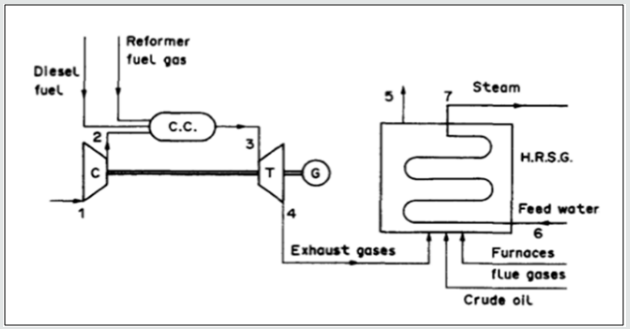
c) Residue gas varies in hydrogen content from around 20 % up to 80 % by volume, depending on what the refinery is producing, with the remainder being methane, with traces of ethane, butane, etc. [96] (Figure 16).
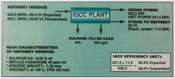
IGCC plant is fully integrated with refinery (Figure 17). A new refinery in Germany has tremendous demands for steam, electricity and process water. A power plant has been built at the refinery which in addition to meeting these needs also burns residue oil from the refinery process [98].
Water Treatment Plant
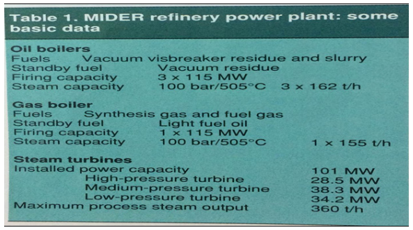
The water treatment plant handles some 2000t/h of raw water to produce demineralized water. The other part is provided by purification of return condensates (400t/h). The heat contained in the return condensate is also used for heating boiler feed water [99]. The special challenges and complexities of the industrial power plant are well illustrated by the IPP facility that is supplying electricity steam water and compressed air to the new MIDER refinery in eastern Germany. The plant burns very heavy and awkward oil residues, must achieve very high levels of reliability and must meet rigorous flue gas cleaning requirements. In addition, it takes its raw water from a polluted river necessitating construction of one of Europe’s largest reverse osmosis water treatment plants [100]. Oil refinery IGCCs turning waste feedstock into product and power. The C-rich syngas properties of many gasification products coal, petroleum, coke, residual oil, wastes or other hydrocarbon compounds, when added to an IGCC, the process converts part of the CO-rich syngas to methanol, and the unconverted gas is used to fuel the combined cycle system [101] Table 1.
Conclusion
Until renewable energy has a great portion of energy pie, it is recommended to work on a wide front of innovative energy systems with high efficiencies and reduced harmful effects on the environment. This front could include some or all of the following technologies:
a. Carbon Capture, Storage and Utilization (CCSU) technologies.
b. Conversion of gas to liquids and chemicals (GTL).
c. Compressed Natural Gas (CNG) and Liquefied Natural Gas (LNG) technologies.
d. Fuel Cell and Hydrogen (FCH).
e. Intelligent Energy Management (energy storage).
f. Repowering and retrofitting.
g. Hybrid Power Generating Systems (fossil and renewable sources).
h. Green Refinery Processes and Systems
Acknowledgement
The author would like to thank Eng. Ahmad Abu-baker and Duaa M.H. Kharouf for the valuable help.
Read More About Lupine Publishers Journal of Environmental & Soil Sciences Please Click on Below Link:
https://lupine-environmental-soil-sciences.blogspot.com/

No comments:
Post a Comment
Note: only a member of this blog may post a comment.