Wednesday 18 December 2019

Lupine Publishers | Persistent Wound Leakage After Total Knee And Hip Arthroplasty

Lupine Publishers | Journal of Orthopaedics

Abstract

In this mini-review the pathogenesis, pathophysiology, diagnosis, treatment and course of prolonged wound leakage after total hip and knee arthroplasty are discussed. It appears there is a disconcerting lack of research and knowledge concerning this topic. Wide variations in definition, classification, diagnosis and treatment hamper patient management, early mobilisation and rehabilitation, as well as the function of the operated joint, severely.

Introduction

The diagnosis and treatment of persistent wound leakage is an important and poorly understood topic in the field of joint arthroplasty. Persistent wound leakage after total knee and hip arthroplasty is associated with a higher risk of developing periprosthetic joint infection (PJI) [1-6]. PJI is a seious complication with great impact on a patient’s physical functioning and quality of life. Moreover, PJI is a high financial burden for society. Additional medical costs of PJI are approximately € 30.000 per patient with even higher societal costs because of productivity loss,home care and informal care provided [7,8]. Unfortunately, there are no evidence-based guidelines for the diagnosis and treatment of persistent wound leakage after joint arthroplasty [6].
Numerous issues hamper the development of sound guidelines. First of all, research on wound leakage is hard, as PJI is used as the major endpoint of wound leakage treatment, which has a low incidence (1,5%)- [9]. Secondly, there is no uniformly accepted definition of wound leakage and when to call it persistent. Clinical practices in orthopedic hospitals vary widely therefore. For that reason pathogenesis, pathophysiology, treatment and course of prolonged wound leakage after arthroplasty are discussed in this mini-review.

Pathogenesis

Following Winter’s original research in 1962, it is now widely accepted that a certain amount of moisture in the wound bed is necessary for optimal healing [10]. The difficulty is determining what that certain amount is and how long it should persist. Inflammation is the body’s normal protective response to any injury (including surgery) or foreign bodies.Acute inflammation follows the early stage of the foreign body response ( protein adsorption) [11,12]. Chemotactic agents within the provisional matrix play a key role in controlling the migration of neutrophils from the vasculature. The travelling leukocytes surrounding the implant become activated in response tothe cytokines released by the platelets e.g PDGF (platelet derived growth factor) and betathromboglobulin [13].
After localization and activation of macrophages and neutrophils tothe site of injury, enzymes are released and then the neutrophils mediated phagocytosis occurs. Theoretically, the phagocytosis should include the procedures of firstly recognizing and attaching to the foreign materials, the nengulfing and degrading them. However, due to the materials size, engulfment and degradation are often not possible,although the process of recognition and attachment occurs. Instead, the implants are coated with opsonins such as complement activated fragments C3b and IgG, which aid the adhesion and activation of neutrophils and macrophages [11]. Macrophages assemble at the implant site, leading to further production of chemoattractive-signalling molecules such as PDGF, tumor necrosis factor (TNF-alpha), interleukin 6 (IL-6), granulocyte-colony-stimulating factor (G-CSF) and granulocyte macrophage colony stimulating factor (GM-CSF), leading to further recruitment of macrophages to the implant site [14]. The foreign body response to bulk implant materials is abberant and prolonged.
At the end-stage of the foreign body response,or when the chronic inflammation occurs, mononuclear cells such as monocytes, lymphocytes and macrophages can present at the implant site. These macrophages which are added by the production of IL-4, IL-13 from Th2 lymphocytes, can fuse together to form a multinucleated foreign body giant cell (FBGC) at the implant surface [15,16]. Next the infiltrated fibroblasts, macrophages and neovascularisation will present within the newly formed granuloma tissue, which is a precursor for forming a fibrous capsule [17,18]. This capsule may contnue to grow following inflammation dueto mechanical motions or chemical leaching exerted in the joint. It was thought that the host response to most bulk biomaterials used in THA was identical and followed these main stages. However, the response tothe wear particles released by different biomaterials over time differ greatly [11,18,19]. Alumnium ceramics are the most biocompatible while Cobalt-Chromium and Ultra-High Molecular Weight Polyethylene (UHMWPE) have reduced bioavailability [18].

Pathophysiology

Total hip arthroplasty is a commonly performed operation and yet little information exists about the duration of wound oozing,the factors associated with this and the implications. Wood et al. Studied 62 consecutive patients undergoing total hip arthroplasty (THA). Time to dryness was associated with wound length (p=0,01), body mass index (BMI;p=0,05) estimated volume of blood in dissected tissues (p=0,05) and length of hospital stay (p=0,02). No association was found with duration of surgery or ASA (American Society of Anaesthesiologists) physical grades [20]. Local factors compromising wound healing include extensive scarring, lymphoedema, poor vascular perfusion and excessive adipose tissue. Systemic comorbidities affecting wound healing include diabetes mellitus, rheumatoid diseases, renal or liver disease, corticosteroid medication, poor nutrition HIV and smoking.Since a history of smoking is associated with a statistically significant increased risk of PJI, many centers use formal smoking cessation programs to assist patients n giving up, preferably before surgery [21].
Patel et al. conducted a retrospective study to determine the risk factors associated with prolonged wound drainage after hip and knee arthroplasty [5]. Risk factors included a BMI>40kg/ square meter, the use of low molecular weight heparin (LMWH) prophylaxis,and a high drain output after THAs. High drain output was the only risk factor associated with prolonged wound drainage after TKAs. HIV infection is also a risk factor for prolonged wound drainage after TKAs [22]. Obesity is a risk factor associated with prolonged operation times,and a higher rate of early postoperative complications, including excessive wound drainage and infection [23]. However,optimal peri-operative glucose control is an important factor in decreasing wound complications for all patients, including those without diabetes [24]. demonstrated that non-diabetic patients were three times more likely to develop PJI if the fasting blood glucose was > 140 mg/dl on the first postoperative day [25]. Proper selection, dosing and timing of prophylactic antibiotics are critical. Most commonly, a first generation cephalosporin is administered within one hour prior to the skin incision.In patients with allergies to penicillin or cephalosporins, clindamycin is an acceptable alternative. For patients with methicillin-resistant Staphylococcus aureus (MRSA) or coagulase-negative Staphylococcus colonisation, vancomycin is used [26].

Diagnosis and Management

Wound healing problems can range from superficial incisional, to deep incisional (outside the joint space) to involving the joint space. Gaine et al. reported a 10% incidence of superficial wound problems in primary TKAs [27,28]. Patel et al. [5] found that each day of prolonged wound drainage increased the risk of deep wound infection by 25% following TKAs. Drainage from the incision one to three days after surgery should be managed by immobilisation in extension, and application of a foam or rolled gauze compressive bandage over the incision. Use of immobilisation and observation should not exceed three days. Wound drainage that persists greater than three days is considered abnormal and should be treated surgically to decrease the chance of subsequent PJI [2,5,22,29].
Aspiration of the joint is necessary if there is a high level of suspicion. The synovial fluid should be analysed for white blood cell (WBC) count and differential.Cultures should also be obtained. There is some consensus with regard to the cell count. In patients with TKAs, a synovial WBC count>1700 cells/ul or a polymorphonuclear neutrophil (PMN) percentage > 65% is rhe recommended threshold for infection [30-32]. In THAs, the recommended thresholds are a synovial WBC count of > 4200 cells/ ul or PMN percentage>80% [33]. During the acute postoperative period,within 6 weeks of surgery, the thresholds are higher with a synovial WBC count>10.000 cells/ul and PMN>89% [34].

Treatment

Prolonged wound leakage after arthroplasty is induced by an inflammatory response , as described above (1,10-16). Conversely, surgical wounds may also show prolonged leakage for other reasons (hematoma,seroma or fatty necrosis) and take longer to heal without development of a PJI. Autoimmune disorders as e.g rheumatoid arthritis and SLE are also associated with prolonged wound leakage [35]. The causes of prolonged wound leakage are poorly understood and studies are scarce and methodologically flaw [6]. However,as expected orthopedic surgeons have been focussed primarily at the association between prolonged wound leakage and PJI.
In the Netherlands,the prevalence of prolonged wound leakage at day 9 after index surgery is about 4% ,2200 patients anually of 55.000 THAs and TKAs. The Dutch Arthoplasty Register reports a total of 3809 THA and 2667 TKA revision surgeries performed in 2015. Revision surgery within 1 year of index surgery was necessary in more than 600 patients and at least 30% of these were PJI related [36]. Persistent wound leakage can be treated by non-surgical and surgical treatment modalities. Non-surgical treatment can consist of relative rest (no exercise and bed rest), pressure bandages,and wound care with sterile bandages.Hospital admission can be required.
Surgical treatment typically consists of debridement, antibiotics and implant retention (DAIR) [37-42]. A DAIR procedure is meant to clean the prosthesis and wound,including break down of the bacterial biofilm, in order to treat the infection and render further infection. Treatment of persistent wound leakage varies considerably among Dutch orthopedic surgeons, as mentioned above [6]. There was a wide variation in classification, definition, diagnosis and treatment of wound leakage. The survey had only a response rate of 18,1%, suggesting wider variations are possible. More than 30 combinations of treatment modalities were used. Remarkably, 23, 4% of responders used antibiotics in the nonsurgical treatment of wound leakage, despite the fact that the efficacy of antibiotic treatment in persistent wound leakage has never been studied. Most respondents (43,8%) convert to surgical treatment if wound leakage is present for ten days after index surgery, implying a non-surgical treatment of 3-7 days. Literature offers litlle guidance but suggests that wound leakage more than 3-5 or 5-9 days after index surgery should be managed by surgical treatment.
Several authors have investigated the effect of DAIR for treatment of wound leakage and reported various results,statements or opinions,generally in favour of early DAIR [2-6], [38-42]. The most recent PJI consensus meetings suggest 5-7 days of wound leakage as the threshold to perform DAIR,but there is no solid evidence forthis statement. As early DAiR is hypothesized tobe helpful in treating or preventing infection and salvaging the implant, the Dutch Leak study will be started soon. This is a controlled randomized study, enrolling 388 patients, with prolonged wound leakage after THA or TKA. Patients are randomized for surgical treatment (DAIR at day 9-10 from index surgery) or continued non-surgical treatment. Primary outcome is the percentage of reoperations for PJI within one year of index surgery. Secondary outcomes are self-reported questionnaires regarding quality of life etc at 3,6, and 12 months after index surgery.

Course and Outcomes

There is a lack of data on the long-term outcome of THAs [43]. Short and medium- term THA studies report substantial improvements in the generic health related quality of life (HRQol) [44-48]. Mariconda et al. conducted a follow-up study to evaluate the quality of life and functionality of 250 patients an average of 16 years (11-23 years) after THA using a validated assessment set including the SF-36 questionnaire,Harris Hip Score,WOMAC score,Functional Comorbidity Index and a study specific questionnaire. The authors report that patients who had undergone THA have impaired long-term self-reported physical quality of life and hip functionality but they still perform better than untreated patients with hip osteoarthritis. However, the level of post-surgical satisfaction is high [43].
considerable proportion of patients report long-term pain after THA or TKA for osteoarthritis.Beswick et al conducted an extensive MEDLINE and EMBASE search of articles published to 2011. Of 1308 articles 115 reported patient-centered pain outcomes. Fourteen articles describing 17 cohorts (6 with hip and 11 with knee replacement) presented appropriate data of pain intensity. The proportion of people with an unfavourable long-term pain outcome in studies ranged from 7% to 23% after hip and 10% to 34% after knee replacements. In the best quality studies,an unfavourable pain outcome was reported in 9% or more of patients after THA and about 20% after TKA [49]. There are no specific short- or long-term studies (>3 years after index surgery) concerning the effect of persistent wound leakage after THA or TKA on quality of life and joint function, whatever the cause or treatment of prolonged oozing.

Conclusion

There is a disconcerting lack of research and knowledge concerning the treatment of prolonged wound leakage after THAs and TKAs, surgeries performed in huge numbers worlwide. With an estimated prevalence of 4%, patients with prolonged wound leakage after arthroplasty also represent a lot of people. Prolonged wound leakage is induced by inflammation, caused by infection immunologic incompability to the implant, autoimmunity as in rheumatoid disorders and SLE, or decreased host defence as in e.g.HIV infection. It will be no surprise that orthopedic surgeons primarily focussed on the association between the low incidence periprosthetic joint infection (1,5%) and prolonged wound leakage after THA or TKA. Recently, a Dutch survey among orthopedic surgeons showed a wide variation in definition, classification, diagnosis and treatment of prolonged wound leakage after arthroplasty.More than 30 combinations of treatment modalities were in use. Remarkably, the unproven use of antibiotics was present in nearly 25% of non-surgical treaments of this issue.
There is no evidence favouring non-surgical treatment above surgical treatment or vice versa. N evertheless, DAIR (debridement, antibiotics and implant retention) is favoured by most orthopedic surgeons at 3-5,5-7 and 9-10 days after index surgery. This arbitrarily and hypothetical timing of DAIR will be studied in an upcoming Dutch trial, the LEAK trial, randomizing 388 patients with prolonged oozing for DAIR at day 9-10 after index surgery versus non-surgical treatment. It is clear that whatever the cause and treatment of persistent wound leakage,early mobilisation and rehabilitation of the patient as well as the function of the joint are hampered severely. There are no sttudies availabale evaluating this topic. It is evident a lot has to be learned in managing and treating prolonged wound leakage after the most common performed arthroplasties in orthopedics.

For more Lupine Publishers Open Access Journals Please visit our website:
For more Open Access Orthopedics and Sports medicine articles Please Click Here:

To Know More About Open Access Publishers Please Click on Lupine Publishers


Follow on Twitter   :  https://twitter.com/lupine_online

Monday 16 December 2019

Lupine Publishers | Climate Resilient Interventions for Improving Food Security in Hill Ecology of Hindu Kush Himalaya

Abstract

The Hindu Kush Himalaya (HKH) region has significant implications for the agro based economies of eight adjoining countries, because of their large dependence on irrigation water originating in the HKH region. However, the HKH region is extremely vulnerable to climate change impacts, which is evident through frequent floods, droughts and retreating glaciers, thus leaving negative consequences for agriculture and livelihood. It is also evident that the traditional farming methods are no longer sustainable to cope with the changing climatic conditions for sustainable production in hill ecology. Therefore, innovative farming technique and irrigation technologies needs to be adopted for mitigating climate change impacts on agriculture and for ensuring food security. Although some pioneer work has been done in developing and promoting improved farming methods and irrigation techniques, but these improvements were mainly focused in major leveled irrigated areas lying downstream of HKH region. Thus, investment on promoting site specific climate resilient practices in hill ecology of HKH was largely overlooked. Addressing these issues, this study is focused on assessment of agricultural production system of Pakistan, as a case example by having 51% area falling in HKH region and reviewed few promising interventions/technologies successfully adopted in downstream irrigated areas that may be equally beneficial for the hill ecology of HKH region. Anecdotal evidence indicates that promotion of these interventions will improve community resilience to climate change and may lead to increased agricultural production and better livelihood for hill ecology of HKH region. This may also improve sustainable irrigation water supply for the irrigated areas downstream.

Introduction

The total area of Hindu Kush Himalaya (HKH) region is ~ 3.44 million sq. km spread over eight countries of Asia. The 51% area of Pakistan (~0.4 million sq. km) falls in HKH region, which form around 12% part of the whole HKH region [1]. Pakistan is home to one quarter (~19%) of the total population (~211 million people) of HKH region with an average population density of 97 persons per sq. km. The second (K2) and ninth (Nanga Parbath) highest peaks of HKH region fall in Pakistan. The agro based economy of HKH region in Pakistan is heavily dependent on the production of vegetables, crops and fruits. Current climate change trends and lack of adequate integrated water resource management strategies are causing huge losses to the country due to frequent droughts and floods [2]. Therefore, traditional farming techniques prevalent in Pakistan are no longer capable to keep up with the rapid climate change variability in the HKH region [3,4] and its downstream basins.
The Indus Basin of Pakistan is comprised of one of the largest contiguous canal irrigation systems in the world that lies at the downstream of HKH, thus prone to frequent climatic disasters [5]. For instance, the recent 2010 floods, originated in HKH region, drowned around one fifth of Pakistan, affected ~20 million people and caused more than US $43 billion impact on the country’s economy [6]. Irrigated agriculture produces around 90% of crop production in Pakistan and contributes more than 21% in the country’s GDP. Moreover, production in Pakistan has global implications, thus may impact on global food security. For instance, Pakistan produces wheat crop greater than the whole Africa and nearly equal to South America. Therefore, agriculture needs to be more wisely managed and traditional farming and irrigation methods needs to be modified according to the changing climatic conditions. This paper reviews some of the salient features of agriculture in Pakistan, its vulnerability to climate change and few promising irrigation technologies capable of improving farming system resilience to climate change.

Salient Features of Pakistan’s Agriculture and their Vulnerability to Climate Change

Land use in Pakistan

The province wise land use is presented in Table 1. The total area of Pakistan is 79.61 million hectares (mha) with 23.40 mha cropped area. The current cultivated area is concentrated in Punjab province with 12.46 mha, which is ~50 % of the total cropped area of Pakistan followed by Sindh Province at ~8 % of country’s cropped area. However, there is 7.82 mha culturable waste area that is largely concentrated in least developed provinces of Khyber Pakhtunkhwa (KP) and Baluchistan, which can be brought under cultivation to enhance food security. The province wise culturable waste areas are 12%, 23%, 64% and 190% of current cultivated lands in Punjab, Sindh, KP and Baluchistan respectively. Therefore, the agro based economies of KP and Baluchistan has greater potential for improvement by cultivating their culturable waste lands.
Table 1: Land use in Pakistan.
lupinepublishers-openaccess-journal-environmental-soil-sciences
The irrigated cropped area in Pakistan is around 18.84 mha (Table 2) according to Agriculture Statistics of Pakistan 2006-07. This includes: wheat 7.34 mha (36.3 % of total); rice 2.58 mha (12.8 % of total); cotton 3.01 mha (15.2 % of total); sugarcane 1.03 mha (5.1 % of total); and fodders 2.00 mha (9.9 % of total). These five crops cover 16.03 mha of total irrigated area in Pakistan, which is 79.32% of the total irrigated area. Therefore, improving water productivity of these five major crops would have major impacts on productivity of irrigated agriculture in Pakistan. Other crops cover 4.17 mha; which constitute around 21.68 % of total irrigated area in Pakistan. The climate change induced floods and droughts significantly impact on crop production, especially during Kharif (summer) season, from both irrigated and rain-fed areas of Pakistan. The current land use methods tend to exacerbate the soil and water degradation and reduce land productivity potential. Similarly damage to standing crops due to lodging caused by heavy winds, water logging and salinity and frequent water stresses at crop critical growth stages causes production losses. Therefore, the traditional farming techniques need to be modified to control crop damage due to climate change induced threats, which is essential for sustainable agriculture in the country.
Table 2: Irrigated cropped area of major crops in Pakistan.
lupinepublishers-openaccess-journal-environmental-soil-sciences

Temporal Water Availability During Rabi and Kharif Seasons In Pakistan

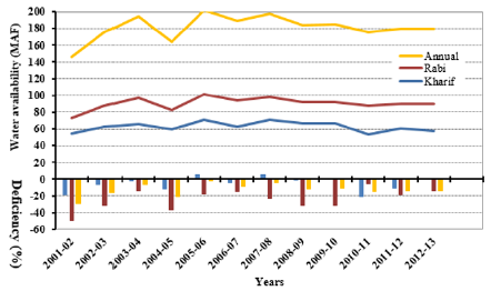
Temporal surface water availability and deficiency during rabi (winter) and kharif (summer) seasons in Pakistan is shown in Figure 1. Temporal changes indicated up to 23% increase and down to 16% decrease in total annual available surface water since 2001 until 2007. However, the variability in total annual available surface water diminished below 5% since 2009 onward. Interestingly a major flood occurred during 2010, but data show insignificant impact on the total water availability (Figure 1). Thus, climate change cannot be judged from the total water availability. However, the frequency, intensity and distribution of rainfall are important parameters to be considered. Similarly, the average deficiency remained around 6.4% during Kharif (summer season) and around 24% during Rabi (winter season) with an average annual water deficiency of around 13% during the last twelve years.
Figure 1: Temporal surface water availability and deficiency during rabi (winter) and kharif (summer) seasons in Pakistan.
lupinepublishers-openaccess-journal-environmental-soil-sciences

Increased Use of Groundwater in Pakistan

Canal water fluctuation and unreliability due to climate change has increased farming community dependence on groundwater during the last decade. The changing trend of water availability is presented in Table 3. The statistics of canal and tube well irrigated area in provinces from 1993-94 to 2010-2011 (Table 3) indicate a decrease of 19% and 26 % in canal irrigated areas and an increase of 26 % and 157% in tube well irrigated areas in Punjab and Sindh provinces respectively. The overall tendency from 1993-94 to 2010- 11 indicated a decrease of 17.5 % in the canal irrigated areas and an increase of 33.5 % in groundwater irrigated areas in Pakistan. The overexploitation of groundwater is coupled with saline water up-coning and disposing of deep brackish groundwater into the soil surface thus causing fertile lands barren in Pakistan. It is therefore essential to reduce groundwater usage by utilizing surface water more efficiently for fulfilling irrigation demands of larger areas. Thus, the traditional irrigation methods need to be modified to more efficient methods to reduce groundwater usage.
Table 3: Temporal change in irrigated area under surface and groundwater in Pakistan.
lupinepublishers-openaccess-journal-environmental-soil-sciences

Climate Resilient Interventions for Improving Food Security in HKH Region

The existing land use, crops, water availability and usage statistics clearly indicate that the traditional farming techniques are not capable to cope with the climate change induced risks. It is therefore essential to adopt suitable climate change risks mitigation interventions for improving food security in HKH region. Few of these interventions/technologies successfully adopted in irrigated leveled lands downstream of HKH are summarized below:

Furrow Bed (Raised Bed) Irrigation Systems

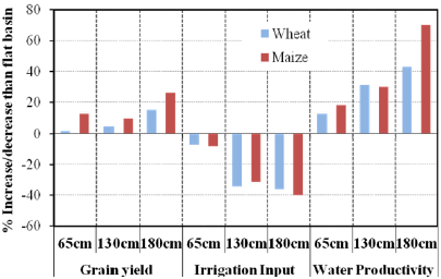
Furrow bed irrigation system is one of the commonly used form of surface irrigation throughout the world (Figure 2) and is generally considered a more water-efficient system compared with the traditional flat basin because of (i) the speed with which water is conveyed to the low end of a field [7]; and (ii) the relatively small proportion of the soil surface is in contact with the flowing water during irrigation than the basin [8]. Furrow bed irrigation system is important in the current climate change scenario of
Figure 2: Advantages of furrow bed over flat basin [11].
lupinepublishers-openaccess-journal-environmental-soil-sciences
Pakistan agriculture in particular and Himalaya region in general due to the following reasons:
a) Furrow bed can save up to 50% irrigation water in comparison with traditional flat basin thus can reduce impact of limited water availability on crops in drought prone areas;
b) Furrows can quickly drain excess floodwater thus can reduce crop damage in flood prone areas;
c) Furrow beds reduce crops lodging by providing safe path and exit to speedy wind currents and greater reinforcement due to strong roots and soil grip;
d) Furrow beds laid perpendicular to slope can increase soil infiltration and ground water recharge by delaying runoff down slope and providing larger surface water storage capacity in furrows;
e) Conservation agricultural practices including minimum tillage, ground cover/mulching etc can be conveniently adopted on furrow beds which reduce soil erosion and soil and water degradation;
f) Furrow beds support mechanized farming thus can increase crop production and can be adapted to technological progress.
The Climate, Energy and Water Research Institute (CEWRI) of Pakistan Agricultural Research Council (PARC) has played a pioneer role in evaluation of furrow beds in Pakistan. Research conducted has shown that furrow beds is effective in improving yield of wheat by 20%, cotton 19%, Maize 58%, rice 26% compared with flat basin or ridge irrigation systems [9,10]. Similarly, crop yield per unit area increases by increasing the bed width. For instance, crop yield of maize showed up to 15% increase while wheat crop showed 26% increase on 180 cm bed size compared with flat basin [11], which was the largest increase noted when compared with other bed sizes given in Figure 2. Water saving of up to 50% in wheat, 30% in maize, 40% in cotton, 29% in rice were reported by N Ahmad et al. [9], Gill et al. [10], Hassan et al. [12]. Increase in water saving by increasing bed has been demonstrated in Figure 2 [9], which shows up to 40% and 36% increase in water saving by adopting 180cm bed size for maize and wheat crops respectively. Furrow bed increase crop yield and reduce irrigation application thus consequently crop water productivity is increased. For instance, an increase in water productivity of up to 70% in maize and up to 43% in wheat were reported by Hassan et al. [12] and Akbar et al. [13]. Impact of bed width on water productivity is illustrated in Figure 2, which shows up to 70% and 43% increase in water productivity for maize and wheat crops respectively compared with flat basin [13].
The CEWRI-PARC in collaboration with Australian Centre for International Agricultural Research (ACIAR) played a pioneer role in adopting furrow bed irrigation system in Maize wheat system of Pakistan. Conservation agricultural practices involving minimum soil disturbance were introduced in the form of permanent raised bed (PRB) farming system. Different bed width and furrow sizes were evaluated and demonstrated at farmer fields. Raised bed machinery imported from Australia was indigenously produced. The furrow bed farming system was disseminated by giving incentive to the farmers in the form of giving subsidies in purchasing raised bed machinery, training and demonstrations in the country. Although there are still issues in the machinery, especially for adopting PRB farming system, but the furrow bed system has been adopted widely for maize, cotton, sugar beat and vegetables crops throughout the country.

Sprinkler Irrigation Systems

In sprinkle irrigation method water is spayed into the air at 70-700 kpa (10-100 psi) pressure that fall on the ground or crop canopy like rainfall [14]. Using sprinkle irrigation system, the crop requirement can be accurately fulfilled through a combination of measures involving careful selection of sprinkle nozzle size, operating pressure and sprinkle spacing, thus adjusting sprinkle application rate to suit the soil infiltration rate. Sprinkle irrigation systems have increased importance for HKH region in the current climate change scenario due to the following reasons:
a) Use limited available water more efficiently as the application efficiency of a well-designed sprinkle system can vary from 60-80% thus can increase crop production and irrigated lands;
b) No land leveling required thus reduce operation cost and protect environment by avoiding cutting and filling of cultivated lands;
c) Irrigation of steep and rolling topography without producing runoff or erosion;
d) Greater potential to increase agricultural production by bringing extra undulating and sloppy HKH terrain under irrigation;
e) Light shower can avoid crop damage due to temperature extremes year around;
f) Timely irrigation of few centimeter using sprinkler irrigation system can double crop yield at critical crop growth stages, especially during wheat germination in HKH region;
g) The pre-sowing irrigation (Rouni) can be applied with sprinkler system for timely planting of crops.
All these factors increase sprinkle irrigation system suitability to the HKH region in the current climate change scenario. However, there are few drawbacks. For instance, these systems are affected by wind and, depending on the size of droplets and the spray trajectory, uniform distribution may be limited. Sprinkle systems have high initial costs and maintenance requirements. They also use high operating pressures, which has large energy requirement. The cost of portable and semi portable system is less but difficult to operate due to movement of laterals. The CEWRI-PARC in collaboration with local industries developed a complete range of rain gun sprinkler irrigation systems, including diesel, electric and PTO-driven pumping systems, couplers, other fittings and joints. To keep the systems portable, the pumping unit along with power unit (diesel engine, electric motor and solar panels) was mounted on a trolley. These systems have been used in the Khanpur Dam area where the rain gun sprinkler irrigation system is being used for establishment of orchards, efficient irrigation of fruits and vegetables, washing of Lychi and citrus, and for cooling and frost control in orchards. Initial investment requirements and unreliable electricity are restricting wider adoption of this technology.
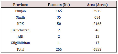
These rain gun sprinkler irrigation systems have been installed in various parts of Pakistan for demonstration and introduction of the technology. In rain fed areas, these systems are being used for supplemental and life-saving irrigations to fruits, vegetables and field crops. The research conducted by CEWRI-PARC resulted in local fabrication of Poly Ethylene (PE) based irrigation system components, sprinklers and high-pressure pumps. Based on research findings and success of pilot-scale installations, the Government of Pakistan launched a National Program entitled “Water Conservation and Productivity Enhancement through High Efficiency Irrigation Systems in Pakistan” during 2007-12. Drip and sprinkler irrigation systems were installed on an area of 6852 acres in all provinces (PARC 2010). The major area was in Punjab and followed by KP. There were 255 farmers benefitted from the project. There were 80 % sprinkler irrigation systems and 20 % were drip system during the period (Table 4).
Table 4: Drip and sprinkler irrigation systems in provinces, installed under the national project (from 2007-2012).
lupinepublishers-openaccess-journal-environmental-soil-sciences

Drip Irrigation Systems

Drip irrigation system applies water close to each plant and the application uniformity depends on the uniformity of discharge from the emitters [14]. It generally comprises of a pumping station, control head, main and sub main lines, lateral lines, emitters, valves and fittings. The drip irrigation system has special agronomical, agro technical and economic advantages that make it a suitable option of irrigation in the HKH and adjoining region. These advantages are as under:
a) Drip irrigation can conveniently and efficiently supply water directly to the individual crop rows or plants, thus can effectively utilize small continuous streams of water in the HKH region;
b) It reduces water requirement by saving up to 50% irrigation water to a young orchard as compared to sprinkle or surface irrigation methods thus can enhance community resilience to drought;
c) It requires less labor, as a well-regulated system can effectively utilize a continuous stream of water, a norm in HKH region, with less farmer supervision thus can increase production;
d) It discourages weeds growth and offers greater control over fertilizer placement and timing thus can save farmer resources;
e) Drip irrigation can be designed for any topography even if the area is rocky with steep slopes and plants are with irregular spacing, which increase its importance for HKH region.
Drip irrigation systems have shown yield gains of up to 100%, water savings of up to 40–80%, and associated fertilizer, pesticide, and labor savings over conventional irrigation systems [15]. The low rate of water application reduces deep percolation losses. The systems have lower energy requirements than sprinkler systems because of lower operating pressure requirement. The water application uniformity of locally developed drip irrigation system was above 85 % [16]. Evaluation of drip systems at CEWRIPARC showed lowest coefficient of variation of locally developed microtube emitters [17] with application uniformity above 85 per cent [16]. This shows that trickle irrigation systems have potential to use scarce water resource more efficiently if designed properly. The evaluations by Ahmad MM et al. [18] indicated that drip system with micro tube emitters can be operated at low pressure head (3.5 m) with an insignificant loss in uniformity as compared to operating at high pressure head (10 m), which can save energy cost, as given in Table 5. This low head drip system is being used for small scale vegetable production in Pakistan.
Table 5: Microtube emitter discharge and water application uniformity at various pressure heads and distances Ahmad et al. [9].
lupinepublishers-openaccess-journal-environmental-soil-sciences
These research outcomes are currently being disseminated through training and demonstration in provinces. The provincial governments are adopting drip/sprinkler systems evidenced through various programs, indicating government commitment for accelerating drip/sprinkler system adoption. By successful adoption of these technologies, more water can be saved or efficiently used along with an increase in yield. The saved water will automatically reduce over exploitation of groundwater and consequently mitigating the secondary salinity by improving overall water use efficiency of the irrigation system. This shows that the system has potential to use scarce water resource more efficiently if designed properly.

Conclusion and Recommendations

a) Lack of adoption of climate change resilient practices in the hill ecology of HKH region is negatively affecting their food security and also have negative implications for the irrigated agriculture downstream in adjoining countries;
b) The 51% area of Pakistan falls in HKH region, thus was considered as a representative case example for analyzing their agricultural production system, growing food security and climate change issues and promising climate resilient interventions mainly adopted in downstream leveled irrigated areas of HKH region;
c) Furrow bed, sprinkler and drip irrigation systems has been shown efficient irrigation methods with multiple advantages thus can be instrumental for improving community resilience to climate change by conserving the declining and uncertain available water resources in the hill ecology of HKH region;

d) However, adoption of these technologies is equally important for improving climate change resilience, food security and livelihood of the hill ecology of HKH region.

For more Lupine Publishers Open Access Journals Please visit our website:
For more Open Access Environment Journal articles Please Click Here:
To Know More About Open Access Publishers Please Click on Lupine Publishers


Follow on Twitter   :  https://twitter.com/lupine_online

Friday 13 December 2019

Lupine Publishers | Utilitarian Value of Selected Mechanical Strength Tests for A Lightweight Floor Construction with A Heating Coil

Lupine Publishers- Trends in Civil Engineering and its Architecture


Abstract


This method of Lightweight floor construction does not require the use of heavy concrete screeds. It consists of a layer of hard thermal insulation on which the tile flooring is directly mounted, usingan adhesive mortar reinforced with a glass fiber mesh. This article summarizes the current results of the strength tests of this radiator model with XPS thermal insulation for bending, compression and point compression with a variety of constructional models. Application in all tests of various types and structures of insulating panels, with the use of glass fiber mesh and without it, allowed us to check and compare the most important strength parameters with different variants. At the same time, the principle of accepting materials that produce results guaranteeing the quality, durability and optimal price of the lightweight floor model with the use of a heating coil was followed.
Keywords: Compressive strength; Bending strength; Lightweight radiant heater; Cement adhesive

Introduction

In 2016 experimental studies on heat flux density and thermal inertia of light radiant heaters, described in [1] and [2], were completed. At the turn of 2016/2017, static shear strength, peel force, pull-off strength, shearing tests, absorbability and frost resistance tests were carried out on insulated EPS polystyrene insulation boards and extruded waffle type XPS with dissipating elements, using polyurethane adhesive [3]. This article describes compressive and bending strength in construction consisting of porcelain tiles, mounted to thermal insulation EPS or XPS through cement adhesive C2S1, both with and without the use of embedded glass fiber mesh. The latest tests on the strength of this radiator heater with XPS thermal insulation for bending, compression and point compression, with or without a glass fiber mesh, and with the use of PE/RT/Al/PE/RT PVC heating pipe with a diameter of 16x2mm, or without it, was made at the Białystok University of Technology.

Description of the measurement stand and research methodology

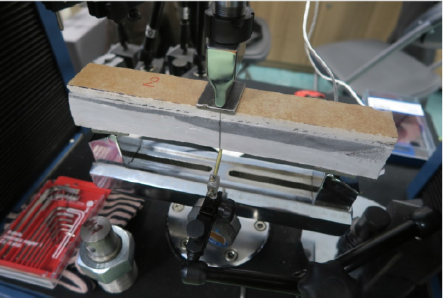
The tests were carried out in the laboratory at the Białystok University of Technology. The research included bending strength, compression and point compression of samples in different variants, using the XPS300 insulating board, a Synthos waffle. Bending strength was tested on the model of the size 45mm(width) x300mm(length) x 50mm(height) with tile, and dimensions 45mm(width)x300mm(length) x42mm(height) without tiles. For bending, we used steel support set with surface 40x45mm and axial spacing of 220mm, and steel pressing stamp of 35 x 47mm, all for 10 models. The first five models were tested with a glass fiber mesh 335 g/m2, embedded in the cement mortar as follow:
1. XPS300 with pipe / Sika Ceram 255 / tile,
2. XPS300 only / Sika Ceram 255 / tile,
3. XPS300 with a groove without pipe / Sika Ceram 255 / tile,
4. XPS300 with pipe / Sika Ceram 255 / no tile,
5. XPS300 only / Sika Ceram 255 / no tile,
The same systems as above were tested but without the use of a mesh.
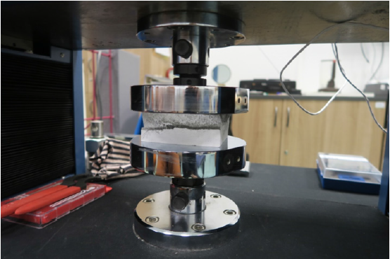
Compressive strength and point compression were tested on a model with dimension 80mm (width) x 100mm (length) x 50mm (height) with tile and 80mm (width) x 100mm (length) x 42mm (height) without tiles, using speed pressure of 4mm / minute. In the compression test, a pressing and supporting steel stamp with a circular surface larger than the surface of the samples was used, and in the point compression test 20x20mm steel stamp was used. The following sample models were tested:
1. XPS Synthos 300 / Sika Ceram 255 with a mesh of 335g/ m2/ tile
2. XPS Synthos 300 / Sika Ceram 255 without a mesh of 335g/m2 / tile
3. XPS Synthos 300 / Sika Ceram 255 with a mesh of 335g/ m2 /no tile
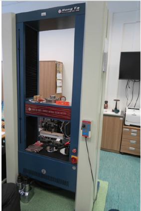
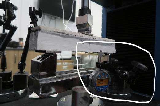
The test stand and tooling are shown in Figure 1-4.
Figure 1: Measuring stand of Hung Ta Instrument Co. Ltd to test the bending and compression strength.
Lupinepublishers-openaccess-journals-Civil-engineering-Architechture
Figure 2: Tooling to measure bending strength.
Lupinepublishers-openaccess-journals-Civil-engineering-Architechture
Figure 3: Digital indicator for measurement of bending Limit Company (marked in the border).
Lupinepublishers-openaccess-journals-Civil-engineering-Architechture
Figure 4: Tooling for measuring compressive strength.
Lupinepublishers-openaccess-journals-Civil-engineering-Architechture

Measurements

Maximum stresses causing destruction of samples and their smallest deflections when testing bending strength Z, compression S and point compression P of a radiant heating model, made of thermal insulation from waffles XPS, according to the construction described in item 2 of this article, is shown in Table 1. Value the Z, S and P strengths of the lightweight floor with the tiles are given under operating conditions (30 days from sample preparation).
Table 1: Results of bending, surface, and point compression tests of a lightweight floor made on XPS insulation.
Lupinepublishers-openaccess-journals-Civil-engineering-Architechture

Analysis of Results

This article closes the cycle of basic tests of mechanical strength over the so-called light-radiant heater in which no type of screed occurs. The aim of the experiments was to determine the possibility of installing this heater in accordance with Article 5.1 of the Construction Polish Law [4]. The model of this radiant heater consists of a thermal insulation layer with grooves in which heating pipes are placed. A coil is inserted into the grooves, and all floor surface is covered with a cement adhesive in a system without metal diffusion plates or polyurethane glue with these metal plates. Adhesives, and their reinforcement in the form of fiberglass mesh, were adopted, which according to the technical description of manufacturers can be used in such radiant heaters on difficult substrates.
Various lightweight heater designs were investigated, using a hard, easy to process thermal insulation with a minimum compressive stress of 200kPa (EPS) and 300kPa (XPS), with a bending strength of minimum 250kPa (EPS) and 300kPa (XPS), according to the Declaration of Properties Utility given by manufacturers and adequately guaranteed standards [5] and [6]. To reinforce the cement adhesive layer, a glass fiber mesh was used on which the most popular type of flooring - tile (stone) was laid. We can use it with underfloor heating or possibly a wall covering in wet rooms. This article summarizes new experiments that were carried out on samples of the entire heating model during bending, surface compression and point compression (puncture), in accordance with the construction described in point. 2., under operating conditions.
The maximum bending force resulting in the destruction of the model with the mesh was on average about 1.1kN, and without it about 0.48kN in different variants - with a mounted coil, without it or with an empty groove. At the same time, this gives a result at least two times better for the radiator construction with mesh reinforcement. The use of a mesh is not so important in compressive strength tests and puncture. The maximum compressive force was 3kN on average, regardless of whether the radiator was reinforced with mesh or not, while the puncture force in the structure with the mesh was on average 3kN, and without it 2.33kN.
Destruction of the samples during the bending strength test occurred at the lowest deflection (elongation) of 10.1mm (sample with mesh) and 8.9mm (sample without mesh) with the axial spacing of supports 220mm. According to the standard [7] for concrete structures calculation of deflections are not necessary if the deflection arrow of a beam, plate or bracket under load exceeds 1/250 of the span. In the previous Polish standard [8] for beams, slabs and flat roofs, the limit values of deflections could not exceed l/200 or 30mm with the construction spans 6-7,5m. In accordance with the above standards, the deflections of the main building structures referring to the tested samples in which the spacing of supports was 220mm can be maximum 220mm/250 = 0.9mm or 220mm/200 = 1.1mm. Deflections in the tests amounted to at least 10 times more, from 9mm to even 32mm. In the case of wooden structures described in the standard [9], the limit deflection arrow is the higest for beams based on 2 supports - l/150 or for the bracket - l/75, including the inverse deflection. It follows that the maximum deflections in relation to our samples can be 220mm/150 = 1.47mm or 220mm/75 = 2.93mm. It is still 3 times lower than the results achieved in the tested samples from 8.9mm upwards. This means that the construction of the light floor is very flexible and is able to bending more, without cracks than all acceptable standard deflections in both, concrete and wooden structures.
The maximum compressive force was not less than 2.6kN, and its average value in operating conditions after 30 days was 3.1kN. This gives us, per m2, a strength of not less than 325kN/m2. At very high compressive force, the samples of the lightweight radiant heater were not destroyed, they were subject only to progressive flattening (deflection). This means there is great resistance of such a radiant heater to any variable payloads found in construction works, including those subjected to dynamic loads. The tested values confirm the compression strength of XPS 300 insulation boards, declared by manufacturers, amounting ≥300kN/m2, in accordance with the standard [6]. This result is very high when we want to compare it to what is projected on the basis of the standard [10]. Utilitarian loads for the rooms, bedrooms of residential buildings and waiting rooms in hospitals, bedrooms in hotels, kitchens and toilets, are only 2kN/m2, or rooms with tables (in schools, cafes, restaurants, canteens, reading rooms, receptions, waiting rooms) 3kN/m2, and the maximum included in this standard with the area generally accessible to the crowd (in public buildings, concert halls, sports halls with stands, terraces, access points and railway platforms) amount to 7.5kN/m2. The maximum tested force under point compression with an area pressure of 4cm2 imitating the legs of a chair or table using a glass fiber mesh was not less than 2.9kN.

Conclusion

The bending strength of a radiant heater without screeds is made higher by using cement adhesives with a glass fiber mesh. As already pointed out in an earlier article [11], the cost of the fiber mesh does not have a significant impact on the price of the entire lightweight radiant heater.
The lightweight, not require screed floor is flexible enough to meet the standard requirements regarding the serviceability limit state at the deflections of concrete structures and wooden structures. It can be dedicated to all types of construction objects, both residential and sacral, sports, and other public utilities, and in industrial buildings with storage and production areas, depending on the loads determined to take into account the intended use and equipment installed. In the case when it can be expected that resonance effects will occur as a result of synchronous, rhythmic movement of people (eg dances, jumps), it is recommended that the calculation model be determined on the basis of a special dynamic analysis contained in [10].
Assuming placing on the floor a table with 4 legs, each with an area of 4cm2, the tested heater is able to transfer the maximum load of over 11kN. During work, when the floor is not yet laid, the maximum point load on the surface of 4cm2 should not exceed 1kN. Under normal conditions of use, there are no such heavy loads.
This article closes the cycle of basic strength tests of a light, thin radiant heater without screeds, and confirms the possibility of its use in all construction objects. I suggest adding to the current experiments new adhesion tests of type C2S2 cement adhesive, with 2 times greater deformability. This will allow a comparison with the results of the tested polyurethane adhesive strength, and give an answer to the question of whether it will be possible to use it outside of buildings, in snow and ice protection systems.

Acknowlegement

The author of the article would like to thank Mrs. Anna Zakowicz and Mr. Tadeusz Chyzy from the Bialystok University of Technology for providing laboratories.


https://lupinepublishers.com/civil-engineering-journal/pdf/TCEIA.MS.ID.000166.pdf

For more Lupine Publishers Open Access Journals Please visit our website:
For more Trends in Civil Engineering and its Architecture articles Please Click Here:
To Know More About Open Access Publishers Please Click on Lupine Publishers


Lupine Publishers | Seismic Strengthening of Masonry Buildings Using Carbon Fiber-Reinforced Polymers

Lupine Publishers | Trends in Civil Engineering and its Architecture


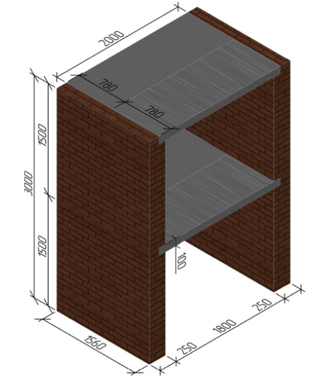
The experimental study on evaluation of seismic resistance of the large-scale model of a two-story fragment of brick building from ceramic bricks on cement mortar was conducted. The dynamic testing of the prototype was carried out on the two-component vibrio plat form, where seismic impacts with the intensity of 7 to 9 according to MSK-64 scale were modelled. During the tests the constant load on floors – 4,5kH/m2 was simulated using dynamic forces to the prototype were simulated. Different options for strengthening of load-bearing brick walls concrete blocks. The dimensions of the two-storey fragment are 2,3x × 1,56 × 3,0m. Using scrims from carbon fibre the slabs at each floor were combined into a single hard disk. During the tests, the horizontal and vertical with composite fabrics, scrims and nets, were considered. Upon the nature of the hysteresis curves the zones of elastic performance of masonry walls at the moment of cracks and destruction were determined. The optimal schemes of brick walls’ strengthening were proposed with the use of ribbons, scrims and nets from carbon cloth. The possibility to increase the stiffness of the slabs disk with composite materials was shown.
Keywords: Large-scale model of building; Brick masonry; Vibration platform; Hysteresis curve; Composite carbon ribbon and net

Introduction


The analysis of earthquakes, performed both in Russia and abroad, allowed us to state that seismic loads belong to the “category of such dynamic effects, exact prediction of the magnitude and nature of which is impossible beforehand” [1]. However, the individual parameters of the effects (the duration of the oscillations (from 10 to 40 s), the number of amplitudes in the record (100- 200), the magnitude of the vertical acceleration - 60-70% of the horizontal acceleration [2] obtained from instrumental records allowed to develop algorithm and methods for experimental studies of seismic resistance of structures made from various materials and thereby to reproduce the real conditions of their loading and propose constructive measures that exclude their collapse and loss of life. However, as noted in [1], “the situation is greatly complicated by the absence of a unified theory of the strength of materials ... under dynamic influences. It is impossible to establish exhaustively reliable methodologies of experimental research” without a well-established criterion for the causes of the materials’ strength breakdown. The result of the absence of this is the need for a large amount of experimental research to solve the strength problem, taking into account the nature of the dynamic effects on the structure and the actual conditions of their loading. This was noted in the early 80-ies of the XX century. Unfortunately, these issues have not been resolved to date with respect to both reinforced concrete and stone structures. Currently in Russia [3,4] criteria strength and plasticity are being developed, which take into account the various mechanisms of destruction brickwork with static action load. Abroad based on the analysis of the results of large volume of research masonry [4,5] developed refined criteria masonry proposed previously [6-9]. In this regard, as noted above, as well as taking into account that for earthquakes brick building get the highest damages in comparison with other systems buildings of reinforced concrete and steel, the only measure the reliability of masonry building with the action of dynamic load is an experiment in the large-scale models using seismic platforms.
Solution to improve the seismic brick walls and eliminate the damage masonry obtained during the impact of seismic forces at earthquakes, is associated with both buildup masonry (to increase the amount of clutching brick with liquid solution) and using different methods to gain more durable materials (plastering nets, metal clips, reinforced concrete frame, etc.). However, the use of these design decisions on strengthening leads to an increase in the mass of structures and, as a consequence of this, the level of seismic load on the construction. Now to enhance the stone structures in the worldwide application find composite materials based on glass- bazalto- and carbon fibers. Effectiveness of the use of these materials to enhance the stone structures is related to the fact that in significantly less weight of their strength and deformation characteristics (breaking strength, elastic modulus and relative elongation at break) either close or not essential different from similar characteristics of the model materials (metal, concrete, solution) used in the strengthening of structures. In addition, composite materials immune to aggressive external factors and their use is possible to enhance the structures almost of any form of the cross-section.

The purpose of work

Evaluation of the influence of various schemes gain carrying brick walls buildings with the use of composite materials on the strength and deformation ability of these buildings in the action of dynamic load modeling the seismic impact of the intensity of 7-9 points on the scale MSK-64.

Prototypes

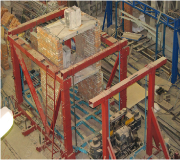
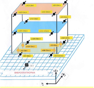
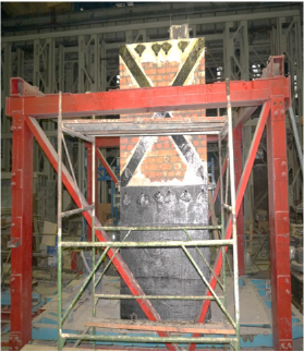
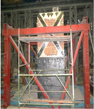
For research was mounted 2-storey fragment of the building (Figure 1). Masonry walls fragment was made of ceramic brick brand M250 on the cement solution brand M150. According to the results tests at the normal adhesion masonry corresponded to I category according to the Norms of СП 14.13330.2014 with Rt ≥0,18MPa (Rt - the value of normal adhesion of bricks with cement mortar). To gain masonry walls were used carbon tape and carbon mesh impregnated styrene-butadien composition, as well as carbon bidirectional and multi axcial fabrics, carbon anchor bundles. Overlap 1st and 2nd floor was made of teams concrete slabs thickness of 100mm in the class of concrete compressive B20. In order to ensure collaboration plates and improve the stiffness disk ceiling in his plane plates were combined with cross ties of carbon tapes. As a load on the plate overlap 1st and 2nd floor was mounted loads mass 300kg. Figure 2 shows a general view of experimental sample set on the vibro platform. Taking into account own weight plates distributed load on the overlap in the level of each floor was 4.5kH/m2. To measure the dynamic parameters impact on the structure and directly dynamic characteristics of the fragment was used instrumentation, installed on the structures and vibro platform (Figure 3).
Figure 1: Measuring stand of Hung Ta Instrument Co. Ltd to test the bending and compression strength.
Lupinepublishers-openaccess-journals-Civil-engineering-Architechture
Figure 2: Tooling to measure bending strength.
Lupinepublishers-openaccess-journals-Civil-engineering-Architechture
Figure 3: Digital indicator for measurement of bending Limit Company (marked in the border).
Lupinepublishers-openaccess-journals-Civil-engineering-Architechture

The test program

Dynamic test of the 2-storey fragment was carried out on a two-component vibrio platform pendulum type. Vibro platform activation was carried out by the vibrio machine type ВИД-12М. Dynamic test included the following steps.
I. Dynamic test on the vibrio platform of not reinforced 2-storey fragment of the building.
II. Dynamic test of the reinforced experimental sample of 2-storey fragment of the building, received damage after the completion of the first stage of the test, using unidirectional carbon tapes, carbon anchor harness and carbon bidirectional (multi axical) fabrics.
III. Dynamic test of the reinforced experimental model with replacement bidirectional carbon fiber for carbon mesh.

The test results and their analysis

The main task of processing records, besides getting maximum value of acceleration fluctuations in the points of registration on the structures fragment and vibrio platform (1-3 levels), was to establish the correlation between the maximum values fluctuations of the design fragment in the above levels and oscillation frequency of the vibrio platform, and to construct graphs of the corresponded amplitude-frequency characteristics (frequency response). In addition, in the process of the results analysis for several modes’ tests were obtained dependences according to the relative offset overlaps the first floor fragment from the inertial impact of the levels of 2 and 3 expressed in the form of parametric graphs. For getting parameter values of fluctuations in the frequency bands were used software filters of Butterworth the 6th order. In the course of treatment records values of the boundary frequencies (lower and upper) of these filters were taken less than 0.2Hz and, accordingly, the more than 0.2Hz than the main frequency of the vibro platform in the relevant mode test. In the course of treatment records to determine the nature of oscillations points on the structures fragment of the building was carried out as a spectral as well as visual analysis of these records. For waveforms horizontal fluctuations in the levels 1-3 in the Central axis track record obtained by four extremes in terms of fragment points in which were sensors, numerically were summarized to get average. In addition to improve the accuracy of processing results, this procedure allows you to divide the horizontal and torsional in terms of fragment fluctuation in its levels [10-13].
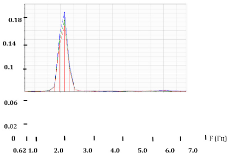
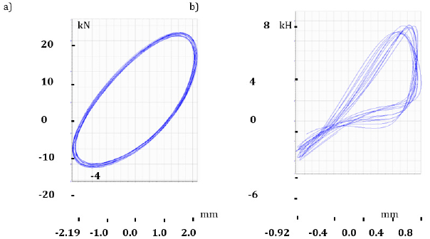
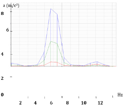
Analysis of the results of the first stage of the test: The results of processing records acceleration of oscillations points on the structures of the building fragment when tested in the specified above the frequency range are presented in the form of graphs (Figure 4). These graphs show the range of acceleration fluctuations in the level 3 (Blue), the level 2 (Green) and in the level 1 (Red) during the test of the fragment in loading regime № 1. In the process of tests at the horizontal acceleration platform 0,782m/ s2 and frequency of 3,8Hz (mode loading № 7), which corresponds to seismic effects of 7 points on the scale MSK-64, there have been cracks in one of the brick walls. Before the appearance of cracks design was represented by a monolithic system, and the schedule of the curves had a view shown in Figure 5a. With further increase in the load, there has been a destruction of compressed support area masonry of one of the walls and appearance of horizontal cracks on the seam (stretching masonry). At the time of the crack appearance hysteresis curve had a type of shown in Figure 5b, i.e., to further increase in dynamic load would lead to complete destruction of the system.
Figure 4: Tooling for measuring compressive strength.
Lupinepublishers-openaccess-journals-Civil-engineering-Architechture
Figure 5: Measuring stand of Hung Ta Instrument Co. Ltd to test the bending and compression strength.
Lupinepublishers-openaccess-journals-Civil-engineering-Architechture
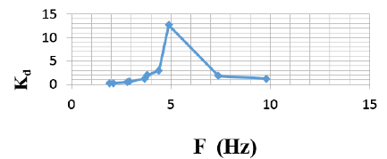
The graph of the Figure 6 shows the dependence of the coefficient of dynamic for relative fluctuations in the upper floors fragment on platform oscillation frequency. The values of the coefficient on the frequencies of 7,4 and 9,8 Hz have been obtained as a result of the spectral analysis of earlier indicated oscillations.
Figure 6: Tooling to measure bending strength.
Lupinepublishers-openaccess-journals-Civil-engineering-Architechture
Prior to the second stage of tests the following work on the strengthening of structures has been done:
a) Masonry was restored and reinforced with concreting to provide a joint work of masonry support area with the basis.
b) Strengthening of masonry walls was provided in the level 1st and 2nd floor with the use of bi-directional carbon fabric (in the level of the 1st floor) and carbon tapes width 300mm (in the level after installation of external reinforcement in the level of overlapping 1st and 2nd floor anchor bundles were installed to provide Mounting of the external reinforcement elements into masonry of the walls.
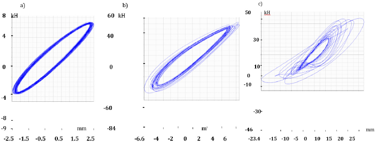
Analysis of data obtained on the second stage of the test: When the levels of dynamic loading are small, and the construction works in the elastic stage hysteresis curves at different levels of loading do not have shift on the horizontal and vertical axis (Figure 8a). At the moment, close to the emergence of cracks in the structures, hysteresis curves take the form shown in Figure 8b. At the time of the destruction of moving in different points of the sample are different: the construction starts working not as a monolithic system, but as a system consisting of the individual sites (the construction “is in the spacing”), and hysteresis curve becomes as shown in Figure 8c. The horizontal acceleration platform 1,9m/ s2 and frequency of 5,0Hz began the process of horizontal cracks appearing in interface walls of the 1st and 2nd floors in the level of overlap 1st floor. The future changes in the load horizontal crack spread all over the length of the Wall. At the same time vertical deformation of masonry in the zone contact the walls of 1st and 2nd floor changed from negative values (compression) on one edge of the Wall to positive values (stretching) - by other side of its edge. As analysis showed the nature of cracks formation in the masonry walls of 2-storey fragment, the lack of relations between the elements of strengthening of the 1st and 2nd floor (there was no interlace of tapes and fabric) led to the appearance of the horizontal cracks in contact the walls of 1st and 2nd floor. On the third stage of the test fabric of carbon fibers in the level of the first floor was replaced on carbon grid with additional installation of vertical tapes width 300mm (Figure 9), which are located continuously along the height of the fragment.
Figure 7: Digital indicator for measurement of bending Limit Company (marked in the border).
Lupinepublishers-openaccess-journals-Civil-engineering-Architechture
Figure 8: Tooling for measuring compressive strength.
Lupinepublishers-openaccess-journals-Civil-engineering-Architechture
Figure 9: Tooling to measure bending strength.
Lupinepublishers-openaccess-journals-Civil-engineering-Architechture
Analysis of data obtained on the third stage of the test, allows you to note the following
From the analysis of the Spectra of horizontal and vertical oscillations, it follows that for the construction fragment, having no damage caused by vibration test:
a) The frequency of their own horizontal fluctuations in the construction fragment on the first form, taking into account the elastic compliance base fragment is set 7,4Hz;
b) The frequency of their own vertical fluctuations in the construction fragment, taking into account the elastic compliance base fragment is set 6Hz.
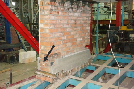
In Figure 10 shows the Spectra of acceleration fluctuations in the level 3 (Blue), the level of 2 (Green) and in the level 1 (Red) during the test fragment in the mode of loading number 8. During the process of test 28 modes of dynamic loading system with changes in the frequency spectrum of 1,3 to 4,7Hz was performed. The amplitude of oscillations platform changed in the range from 0.8 to 21мм. Vibration amplitude of the top of the experimental sample was changed in the range from 2,0 to 34,7мм. Acceleration maximum value of the vibro platform was 6,5m/s2 that was more than one and a half times of the standard value of acceleration for the site with range 9. at the same time acceleration at the top point of 2-storey fragment (plate overlap over the 2nd floor) at the moment, close to the destruction of masonry, changed from 6,5m/ s2 (23rd mode loading) to 13,6m/s2 (the time of the destruction of masonry - 28th loading mode). During the 23rd loading mode there was the beginning of the destruction of boundary-value sites of masonry near the support zone (Figure 11). At the moment, close to the destruction, there was a crushing brick in the corner areas of the walls in the level of supporting on vibro platform, that. ie. in areas with maximum stress compression of masonry. At the same time because of the cyclic changes of the load sign the process of destruction included masonry bundle followed by its crumpling. As seen on Figure 11, the presence of external reinforcement from the outer side of the walls of the as seen on Figure 11, the presence of external reinforcement from the outer side of the walls of the building fragment excluded masonry uniform compression on the thickness of the Wall. In this case the maximum voltage compression took place inside the corner zone of the walls.
Figure 10: Digital indicator for measurement of bending Limit Company (marked in the border).
Lupinepublishers-openaccess-journals-Civil-engineering-Architechture
Figure 11: Tooling for measuring compressive strength.
Lupinepublishers-openaccess-journals-Civil-engineering-Architechture

Conclusion


a) The use of the external reinforcement on the basis of composite materials to enhance the Stone constructions built in seismic dangerous regions, allows you to significantly reduce the mass of structures in comparison with widely applicable currently methods based on the use of the model of metal and reinforced concrete structures, and thus reduce the level of seismic load on the construction.
b) Application as an external reinforcement of carbon tapes, fabrics, Nets and anchor harness to enhance the Stone costructions can significantly improve Seismic resistance of constructions.
c) During the 3d test stage of 2-storey building fragment the used scheme of masonry strengthening showed its high efficiency.
d) In the design of buildings brick walls strengthening with the use of composite materials on the basis of carbon fiber it is recommended to set the elements of strengthening from both inner and outer sides of the walls that will allow more evenly distribute the internal efforts caused by dynamic load as on the length of the Wall, and on the thickness of masonry.
e) As a result of tests composite materials in the form of carbon tapes, carbon grid impregnated styrene-butadiene composition, of carbon anchor harness are recommended as the elements of the external reinforcement Stone structures in order to improve their carrier ability and seismic resistance. These materials can be used in the regions with seismic range 7-9 points on the scale MSK-64.


https://lupinepublishers.com/civil-engineering-journal/pdf/TCEIA.MS.ID.000167.pdf


For more Lupine Publishers Open Access Journals Please visit our website:
For more Trends in Civil Engineering and its Architecture articles Please Click Here:

To Know More About Open Access Publishers Please Click on Lupine Publishers