Lupine Publishers | Current Investigations in Agriculture and Current Research
Abstract
The hydraulic ram, sometimes abbreviated hydram. It is a simple automatic device which utilizes the kinetic energy of water falling a moderate height to raise a part of it to a much greater height.
Where it can be used
The device can be used wherever a stream of water flows with a minimum of about 1m fall in altitude.
History
The first working model of a hydraulic ram was developed by Montgolfier in the year 1796.
Introduction
Like the windmill, the hydraulic ram experienced a period of popularity in industrialized countries, followed by a decline due to the large-scale development in generation and distribution of economical electrical energy. In developing countries, however, the difficulty in conveying electrical energy to remote hilly areas and the shortage of petroleum fuels have focused the importance of hydraulic rams for small-scale lift irrigation and rural water supply.
Hilly areas are often deprived of irrigation facilities due to uneven topography and non-availability of conventional sources of energy. Studies shows that hydraulic rams as a potential means of irrigation in the hilly areas. Hydraulic rams could also be used with advantage in the hilly regions of most states in India and other developing countries. The source of supply of water for operating a hydraulic ram may be a stream, a spring or an irrigation canal. In the mountainous regions of India and other developing countries, there are numerous sites where hydraulic rams could be installed, thus reducing human drudgery in carrying head loads of drinking water along steep slopes or turning unproductive and unused lands to efficient farming units. The simplicity of construction and the automatic operation of the hydraulic ram make it especially adapted to remote rural areas which often have problems of nonavailability of commercial energy sources such as electricity and diesel and lack of skilled technicians for maintenance and repair of engines/motors and pumps.
Specific applications of hydraulic ram
a) To lift a part of the flow of hillside spring, stream, rivulet to irrigate adjacent slopy lands.
b) To lift water for drinking water supply in villages.
c) To provide water supply to small industrial establishments and fish ponds located in hilly areas.
d) To feed water to a high-level field channel by installing the ram downstream of a weir or drop structure in a canal system. This will increase the command area of a canal system.
e) To boost the discharge of lift irrigation schemes using engine or electric motor operated pumping sets, to take a part of the pump discharge to higher elevations for irrigation.
Principle of operation
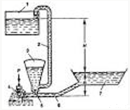
The hydraulic ram works on the principle of the water hammer (Figure 1). The water hammer is a phenomenon resulting in an instant rise in pressure of the water flowing in a pipe, due to sudden stoppage of the motion. The cycle of operation in a hydraulic ram is as follows. The ram is started by opening the gate valve on the drive pipe. Water flows from the supply source, through the drive pipe, to the waste valve. The waste valve being open, water is free to escape, and flow is set up along the drive pipe. The velocity of flow is increased under the influence of the supply head, until the dynamic pressure on the side of the waste valve becomes sufficiently great to overcome its weight. The valve then closes rapidly. The supply column suffers a consequent retardation which gives rise to rapid increase of pressure in the valve box. This opens the delivery valve into the air vessel, compresses the air in it and water escapes through the discharge pipe. As soon as the momentum of the supply column is spent, the compressed air and the water under pressure closes the delivery valve. A backward motion of water occurs in the intake chamber and drive pipe, causing a negative pressure in the valve chamber. The waste valve, which is hinged on a steep angle in the valve box, falls back due to the vacuum and its own mass and allows water to flow out. As the velocity of water in the drive pipe increases, the gate valve again closes suddenly, and the cycle is repeated. The frequency of operation varies from 25 to 100 times a minute. In order to develop maximum impulse, the supply pipe should be as long as possible.
Figure 1: Hydraulic Ram.

1.Discharge pool, 2. Discharge pipe, 3. Air vessel, 4. Waste valve, 5. Delivery valve, 6. Supply pipe,7. Supply channel, H=Supply head, hd =Delivery head
Advantages
a) The hydraulic ram is simple in construction and operation.
b) It does not incur any running cost, as it utilizes the energy of water available freely, and no fuel or electricity is required.
c) It has only two moving parts, the waste valve and the delivery valve, both of which are lubricated by the water itself. Thus, no separate arrangement for lubrication is required.
d) It ensures continuous water supply, as it operates throughout the day and night.
e) It works efficiently over a wide range of flows in the supply stream.
f) It does not cause any pollution.
Disadvantages
a) For the installation of hydraulic ram, a minimum fall of 1 m from the stream to the ram is required.
b) The hydraulic ram can lift only a small part of the flow which is fed to it (Generally 1/20th to 1/10th of the water supplied through to drive pipe).
c) Since the ram works all 24hours in a day, a storage tank is necessary to store the night supply.
d) Due to comparatively high initial investment, it is more adapted to ownership by small groups of farmers who can share the water amongst themselves, or by public agencies under water supply schemes.
Size of drive pipe
The size of the drive pipe is so designed that the rate of flow of water through it is at least three times the rate of discharge through the delivery pipe. The approximate size of the drive pipe may be computed from the following relationship:
D=√{0.5(Q+H)}-………………………3
Where D= diameter of the supply pipe, m
Q and H are as defined earlier
The range in values of the length of the supply pipe is estimated from the following relationship:
L=1.5(hd-H) to 3(hd-H)
A thumb rule commonly used to keep the ratio of diameter to the length of drive pipe as 1:500. Longer drive pipes do not increase the efficiency of the ram substantially but permit the pump to operate at less strokes per minute, which results in less wear to the valve and longer operating life. Heavy galvanized pipes with leak proof points are essential for the drive pipe as it has to withstand high pressure due to water hammering. The drive pipe should be straight, as far as possible, and without any elbows. Generally, the size of the drive pipe and that of the intake of the ram are kept the same.
Delivery pipe
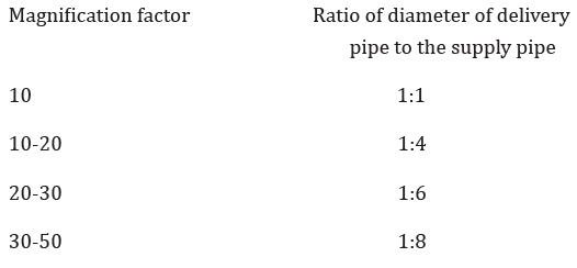
The discharge of the hydraulic ram is inversely proportional to the delivery head. The discharge pipe may have a uniform size if the water is tapped only at the highest point. If, however the water is to be taken out at intermediate points, a variable size delivery pipeline may be used. A larger size pipe is used in the lower section to reduce the head loss by friction and to obtain a higher rate of discharge. The pipe size may be reduced to steps at each point the flow is tapped. The size of the delivery pipeline is to match the magnification factor and the size of the supply pipe approximately, as follows:

Medium quality galvanized iron, rigid PVC or high-density polyethylene (HDPE) pipes may be used for the delivery pipeline. In case of polyethylene pipe, it is desirable to lay it underground to ensure durability. Bursting of the delivery pipe due to poor quality is common cause of failure of hydraulic ram installations. BIS standards are a good guidance in selecting HDPE, PVC, GI pipes. In high head installations, it may be advantageous to have the lower 1/3rd or half length of the pipeline of GI, and the rest of HDPE, in view of the ability of the GI pipe to withstand high pressure. If the delivery pipe has any high points or abrupt turns where air might get trapped, an air valve or air vent is necessary.
Read More Lupine Publishers Agriculture Journal Article:

No comments:
Post a Comment
Note: only a member of this blog may post a comment.