Lupine Publishers | Trends in Civil Engineering and its Architecture
The experimental study on evaluation of seismic resistance of the large-scale model of a two-story fragment of brick building from ceramic bricks on cement mortar was conducted. The dynamic testing of the prototype was carried out on the two-component vibrio plat form, where seismic impacts with the intensity of 7 to 9 according to MSK-64 scale were modelled. During the tests the constant load on floors – 4,5kH/m2 was simulated using dynamic forces to the prototype were simulated. Different options for strengthening of load-bearing brick walls concrete blocks. The dimensions of the two-storey fragment are 2,3x × 1,56 × 3,0m. Using scrims from carbon fibre the slabs at each floor were combined into a single hard disk. During the tests, the horizontal and vertical with composite fabrics, scrims and nets, were considered. Upon the nature of the hysteresis curves the zones of elastic performance of masonry walls at the moment of cracks and destruction were determined. The optimal schemes of brick walls’ strengthening were proposed with the use of ribbons, scrims and nets from carbon cloth. The possibility to increase the stiffness of the slabs disk with composite materials was shown.
Keywords: Large-scale model of building; Brick masonry; Vibration platform; Hysteresis curve; Composite carbon ribbon and net
The analysis of earthquakes, performed both in Russia and
abroad, allowed us to state that seismic loads belong to the
“category of such dynamic effects, exact prediction of the magnitude
and nature of which is impossible beforehand” [1]. However, the
individual parameters of the effects (the duration of the oscillations
(from 10 to 40 s), the number of amplitudes in the record (100-
200), the magnitude of the vertical acceleration - 60-70% of the
horizontal acceleration [2] obtained from instrumental records
allowed to develop algorithm and methods for experimental
studies of seismic resistance of structures made from various
materials and thereby to reproduce the real conditions of their
loading and propose constructive measures that exclude their
collapse and loss of life. However, as noted in [1], “the situation
is greatly complicated by the absence of a unified theory of the
strength of materials ... under dynamic influences. It is impossible
to establish exhaustively reliable methodologies of experimental
research” without a well-established criterion for the causes of the
materials’ strength breakdown. The result of the absence of this is
the need for a large amount of experimental research to solve the
strength problem, taking into account the nature of the dynamic
effects on the structure and the actual conditions of their loading.
This was noted in the early 80-ies of the XX century. Unfortunately,
these issues have not been resolved to date with respect to both
reinforced concrete and stone structures. Currently in Russia [3,4]
criteria strength and plasticity are being developed, which take into
account the various mechanisms of destruction brickwork with
static action load. Abroad based on the analysis of the results of
large volume of research masonry [4,5] developed refined criteria
masonry proposed previously [6-9]. In this regard, as noted above,
as well as taking into account that for earthquakes brick building get
the highest damages in comparison with other systems buildings
of reinforced concrete and steel, the only measure the reliability of
masonry building with the action of dynamic load is an experiment
in the large-scale models using seismic platforms.
Solution to improve the seismic brick walls and eliminate the damage masonry obtained during the impact of seismic forces at earthquakes, is associated with both buildup masonry (to increase the amount of clutching brick with liquid solution) and using different methods to gain more durable materials (plastering nets, metal clips, reinforced concrete frame, etc.). However, the use of these design decisions on strengthening leads to an increase in the mass of structures and, as a consequence of this, the level of seismic load on the construction. Now to enhance the stone structures in the worldwide application find composite materials based on glass- bazalto- and carbon fibers. Effectiveness of the use of these materials to enhance the stone structures is related to the fact that in significantly less weight of their strength and deformation characteristics (breaking strength, elastic modulus and relative elongation at break) either close or not essential different from similar characteristics of the model materials (metal, concrete, solution) used in the strengthening of structures. In addition, composite materials immune to aggressive external factors and their use is possible to enhance the structures almost of any form of the cross-section.
I. Dynamic test on the vibrio platform of not reinforced 2-storey fragment of the building.
II. Dynamic test of the reinforced experimental sample of 2-storey fragment of the building, received damage after the completion of the first stage of the test, using unidirectional carbon tapes, carbon anchor harness and carbon bidirectional (multi axical) fabrics.
III. Dynamic test of the reinforced experimental model with replacement bidirectional carbon fiber for carbon mesh.
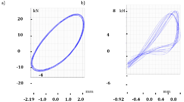
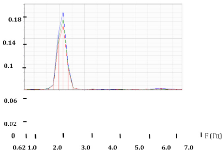
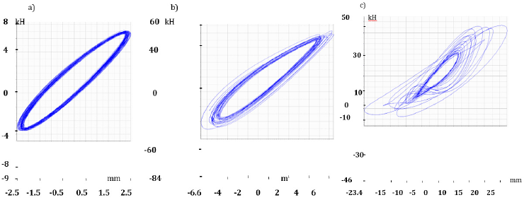
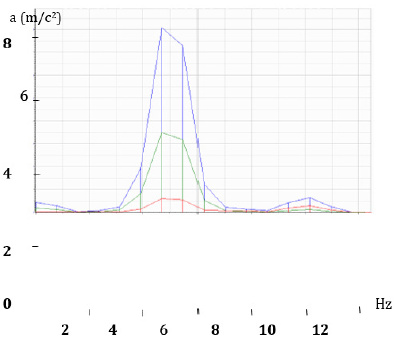
Analysis of the results of the first stage of the test: The results of processing records acceleration of oscillations points on the structures of the building fragment when tested in the specified above the frequency range are presented in the form of graphs (Figure 4). These graphs show the range of acceleration fluctuations in the level 3 (Blue), the level 2 (Green) and in the level 1 (Red) during the test of the fragment in loading regime № 1. In the process of tests at the horizontal acceleration platform 0,782m/ s2 and frequency of 3,8Hz (mode loading № 7), which corresponds to seismic effects of 7 points on the scale MSK-64, there have been cracks in one of the brick walls. Before the appearance of cracks design was represented by a monolithic system, and the schedule of the curves had a view shown in Figure 5a. With further increase in the load, there has been a destruction of compressed support area masonry of one of the walls and appearance of horizontal cracks on the seam (stretching masonry). At the time of the crack appearance hysteresis curve had a type of shown in Figure 5b, i.e., to further increase in dynamic load would lead to complete destruction of the system.
Prior to the second stage of tests the following work on the strengthening of structures has been done:
a) Masonry was restored and reinforced with concreting to provide a joint work of masonry support area with the basis.
b) Strengthening of masonry walls was provided in the level 1st and 2nd floor with the use of bi-directional carbon fabric (in the level of the 1st floor) and carbon tapes width 300mm (in the level after installation of external reinforcement in the level of overlapping 1st and 2nd floor anchor bundles were installed to provide Mounting of the external reinforcement elements into masonry of the walls.
Analysis of data obtained on the second stage of the test: When the levels of dynamic loading are small, and the construction works in the elastic stage hysteresis curves at different levels of loading do not have shift on the horizontal and vertical axis (Figure 8a). At the moment, close to the emergence of cracks in the structures, hysteresis curves take the form shown in Figure 8b. At the time of the destruction of moving in different points of the sample are different: the construction starts working not as a monolithic system, but as a system consisting of the individual sites (the construction “is in the spacing”), and hysteresis curve becomes as shown in Figure 8c. The horizontal acceleration platform 1,9m/ s2 and frequency of 5,0Hz began the process of horizontal cracks appearing in interface walls of the 1st and 2nd floors in the level of overlap 1st floor. The future changes in the load horizontal crack spread all over the length of the Wall. At the same time vertical deformation of masonry in the zone contact the walls of 1st and 2nd floor changed from negative values (compression) on one edge of the Wall to positive values (stretching) - by other side of its edge. As analysis showed the nature of cracks formation in the masonry walls of 2-storey fragment, the lack of relations between the elements of strengthening of the 1st and 2nd floor (there was no interlace of tapes and fabric) led to the appearance of the horizontal cracks in contact the walls of 1st and 2nd floor. On the third stage of the test fabric of carbon fibers in the level of the first floor was replaced on carbon grid with additional installation of vertical tapes width 300mm (Figure 9), which are located continuously along the height of the fragment.
Analysis of data obtained on the third stage of the test, allows you to note the following
From the analysis of the Spectra of horizontal and vertical oscillations, it follows that for the construction fragment, having no damage caused by vibration test:
a) The frequency of their own horizontal fluctuations in the construction fragment on the first form, taking into account the elastic compliance base fragment is set 7,4Hz;
b) The frequency of their own vertical fluctuations in the construction fragment, taking into account the elastic compliance base fragment is set 6Hz.
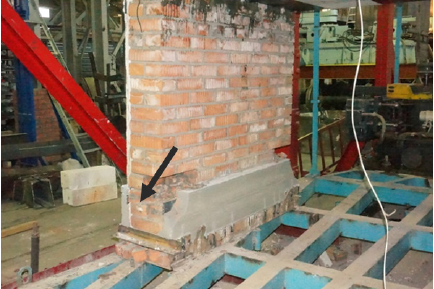
In Figure 10 shows the Spectra of acceleration fluctuations in the level 3 (Blue), the level of 2 (Green) and in the level 1 (Red) during the test fragment in the mode of loading number 8. During the process of test 28 modes of dynamic loading system with changes in the frequency spectrum of 1,3 to 4,7Hz was performed. The amplitude of oscillations platform changed in the range from 0.8 to 21мм. Vibration amplitude of the top of the experimental sample was changed in the range from 2,0 to 34,7мм. Acceleration maximum value of the vibro platform was 6,5m/s2 that was more than one and a half times of the standard value of acceleration for the site with range 9. at the same time acceleration at the top point of 2-storey fragment (plate overlap over the 2nd floor) at the moment, close to the destruction of masonry, changed from 6,5m/ s2 (23rd mode loading) to 13,6m/s2 (the time of the destruction of masonry - 28th loading mode). During the 23rd loading mode there was the beginning of the destruction of boundary-value sites of masonry near the support zone (Figure 11). At the moment, close to the destruction, there was a crushing brick in the corner areas of the walls in the level of supporting on vibro platform, that. ie. in areas with maximum stress compression of masonry. At the same time because of the cyclic changes of the load sign the process of destruction included masonry bundle followed by its crumpling. As seen on Figure 11, the presence of external reinforcement from the outer side of the walls of the as seen on Figure 11, the presence of external reinforcement from the outer side of the walls of the building fragment excluded masonry uniform compression on the thickness of the Wall. In this case the maximum voltage compression took place inside the corner zone of the walls.
a) The use of the external reinforcement on the basis of
composite materials to enhance the Stone constructions built
in seismic dangerous regions, allows you to significantly reduce
the mass of structures in comparison with widely applicable
currently methods based on the use of the model of metal and
reinforced concrete structures, and thus reduce the level of
seismic load on the construction.
b) Application as an external reinforcement of carbon tapes, fabrics, Nets and anchor harness to enhance the Stone costructions can significantly improve Seismic resistance of constructions.
c) During the 3d test stage of 2-storey building fragment the used scheme of masonry strengthening showed its high efficiency.
d) In the design of buildings brick walls strengthening with the use of composite materials on the basis of carbon fiber it is recommended to set the elements of strengthening from both inner and outer sides of the walls that will allow more evenly distribute the internal efforts caused by dynamic load as on the length of the Wall, and on the thickness of masonry.
e) As a result of tests composite materials in the form of carbon tapes, carbon grid impregnated styrene-butadiene composition, of carbon anchor harness are recommended as the elements of the external reinforcement Stone structures in order to improve their carrier ability and seismic resistance. These materials can be used in the regions with seismic range 7-9 points on the scale MSK-64.
https://lupinepublishers.com/civil-engineering-journal/pdf/TCEIA.MS.ID.000167.pdf
The experimental study on evaluation of seismic resistance of the large-scale model of a two-story fragment of brick building from ceramic bricks on cement mortar was conducted. The dynamic testing of the prototype was carried out on the two-component vibrio plat form, where seismic impacts with the intensity of 7 to 9 according to MSK-64 scale were modelled. During the tests the constant load on floors – 4,5kH/m2 was simulated using dynamic forces to the prototype were simulated. Different options for strengthening of load-bearing brick walls concrete blocks. The dimensions of the two-storey fragment are 2,3x × 1,56 × 3,0m. Using scrims from carbon fibre the slabs at each floor were combined into a single hard disk. During the tests, the horizontal and vertical with composite fabrics, scrims and nets, were considered. Upon the nature of the hysteresis curves the zones of elastic performance of masonry walls at the moment of cracks and destruction were determined. The optimal schemes of brick walls’ strengthening were proposed with the use of ribbons, scrims and nets from carbon cloth. The possibility to increase the stiffness of the slabs disk with composite materials was shown.
Keywords: Large-scale model of building; Brick masonry; Vibration platform; Hysteresis curve; Composite carbon ribbon and net
Introduction
Solution to improve the seismic brick walls and eliminate the damage masonry obtained during the impact of seismic forces at earthquakes, is associated with both buildup masonry (to increase the amount of clutching brick with liquid solution) and using different methods to gain more durable materials (plastering nets, metal clips, reinforced concrete frame, etc.). However, the use of these design decisions on strengthening leads to an increase in the mass of structures and, as a consequence of this, the level of seismic load on the construction. Now to enhance the stone structures in the worldwide application find composite materials based on glass- bazalto- and carbon fibers. Effectiveness of the use of these materials to enhance the stone structures is related to the fact that in significantly less weight of their strength and deformation characteristics (breaking strength, elastic modulus and relative elongation at break) either close or not essential different from similar characteristics of the model materials (metal, concrete, solution) used in the strengthening of structures. In addition, composite materials immune to aggressive external factors and their use is possible to enhance the structures almost of any form of the cross-section.
The purpose of work
Evaluation of the influence of various schemes gain carrying brick walls buildings with the use of composite materials on the strength and deformation ability of these buildings in the action of dynamic load modeling the seismic impact of the intensity of 7-9 points on the scale MSK-64.Prototypes
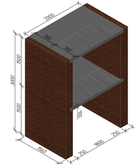
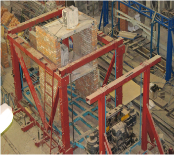
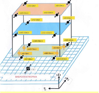
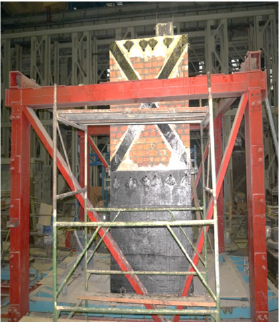
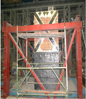
For research was mounted 2-storey fragment of the building (Figure 1). Masonry walls fragment was made of ceramic brick brand M250 on the cement solution brand M150. According to the results tests at the normal adhesion masonry corresponded to I category according to the Norms of СП 14.13330.2014 with Rt ≥0,18MPa (Rt - the value of normal adhesion of bricks with cement mortar). To gain masonry walls were used carbon tape and carbon mesh impregnated styrene-butadien composition, as well as carbon bidirectional and multi axcial fabrics, carbon anchor bundles. Overlap 1st and 2nd floor was made of teams concrete slabs thickness of 100mm in the class of concrete compressive B20. In order to ensure collaboration plates and improve the stiffness disk ceiling in his plane plates were combined with cross ties of carbon tapes. As a load on the plate overlap 1st and 2nd floor was mounted loads mass 300kg. Figure 2 shows a general view of experimental sample set on the vibro platform. Taking into account own weight plates distributed load on the overlap in the level of each floor was 4.5kH/m2. To measure the dynamic parameters impact on the structure and directly dynamic characteristics of the fragment was used instrumentation, installed on the structures and vibro platform (Figure 3).
Figure 1: Measuring stand of Hung Ta Instrument Co. Ltd to test the bending and compression strength.

The test program
Dynamic test of the 2-storey fragment was carried out on a two-component vibrio platform pendulum type. Vibro platform activation was carried out by the vibrio machine type ВИД-12М. Dynamic test included the following steps.I. Dynamic test on the vibrio platform of not reinforced 2-storey fragment of the building.
II. Dynamic test of the reinforced experimental sample of 2-storey fragment of the building, received damage after the completion of the first stage of the test, using unidirectional carbon tapes, carbon anchor harness and carbon bidirectional (multi axical) fabrics.
III. Dynamic test of the reinforced experimental model with replacement bidirectional carbon fiber for carbon mesh.
The test results and their analysis
The main task of processing records, besides getting maximum value of acceleration fluctuations in the points of registration on the structures fragment and vibrio platform (1-3 levels), was to establish the correlation between the maximum values fluctuations of the design fragment in the above levels and oscillation frequency of the vibrio platform, and to construct graphs of the corresponded amplitude-frequency characteristics (frequency response). In addition, in the process of the results analysis for several modes’ tests were obtained dependences according to the relative offset overlaps the first floor fragment from the inertial impact of the levels of 2 and 3 expressed in the form of parametric graphs. For getting parameter values of fluctuations in the frequency bands were used software filters of Butterworth the 6th order. In the course of treatment records values of the boundary frequencies (lower and upper) of these filters were taken less than 0.2Hz and, accordingly, the more than 0.2Hz than the main frequency of the vibro platform in the relevant mode test. In the course of treatment records to determine the nature of oscillations points on the structures fragment of the building was carried out as a spectral as well as visual analysis of these records. For waveforms horizontal fluctuations in the levels 1-3 in the Central axis track record obtained by four extremes in terms of fragment points in which were sensors, numerically were summarized to get average. In addition to improve the accuracy of processing results, this procedure allows you to divide the horizontal and torsional in terms of fragment fluctuation in its levels [10-13].Analysis of the results of the first stage of the test: The results of processing records acceleration of oscillations points on the structures of the building fragment when tested in the specified above the frequency range are presented in the form of graphs (Figure 4). These graphs show the range of acceleration fluctuations in the level 3 (Blue), the level 2 (Green) and in the level 1 (Red) during the test of the fragment in loading regime № 1. In the process of tests at the horizontal acceleration platform 0,782m/ s2 and frequency of 3,8Hz (mode loading № 7), which corresponds to seismic effects of 7 points on the scale MSK-64, there have been cracks in one of the brick walls. Before the appearance of cracks design was represented by a monolithic system, and the schedule of the curves had a view shown in Figure 5a. With further increase in the load, there has been a destruction of compressed support area masonry of one of the walls and appearance of horizontal cracks on the seam (stretching masonry). At the time of the crack appearance hysteresis curve had a type of shown in Figure 5b, i.e., to further increase in dynamic load would lead to complete destruction of the system.
Figure 5: Measuring stand of Hung Ta Instrument Co. Ltd to test the bending and compression strength.
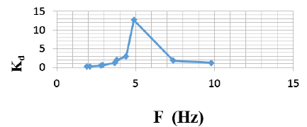
The graph of the Figure 6 shows the dependence of the
coefficient of dynamic for relative fluctuations in the upper floors
fragment on platform oscillation frequency. The values of the
coefficient on the frequencies of 7,4 and 9,8 Hz have been obtained
as a result of the spectral analysis of earlier indicated oscillations.
Prior to the second stage of tests the following work on the strengthening of structures has been done:
a) Masonry was restored and reinforced with concreting to provide a joint work of masonry support area with the basis.
b) Strengthening of masonry walls was provided in the level 1st and 2nd floor with the use of bi-directional carbon fabric (in the level of the 1st floor) and carbon tapes width 300mm (in the level after installation of external reinforcement in the level of overlapping 1st and 2nd floor anchor bundles were installed to provide Mounting of the external reinforcement elements into masonry of the walls.
Analysis of data obtained on the second stage of the test: When the levels of dynamic loading are small, and the construction works in the elastic stage hysteresis curves at different levels of loading do not have shift on the horizontal and vertical axis (Figure 8a). At the moment, close to the emergence of cracks in the structures, hysteresis curves take the form shown in Figure 8b. At the time of the destruction of moving in different points of the sample are different: the construction starts working not as a monolithic system, but as a system consisting of the individual sites (the construction “is in the spacing”), and hysteresis curve becomes as shown in Figure 8c. The horizontal acceleration platform 1,9m/ s2 and frequency of 5,0Hz began the process of horizontal cracks appearing in interface walls of the 1st and 2nd floors in the level of overlap 1st floor. The future changes in the load horizontal crack spread all over the length of the Wall. At the same time vertical deformation of masonry in the zone contact the walls of 1st and 2nd floor changed from negative values (compression) on one edge of the Wall to positive values (stretching) - by other side of its edge. As analysis showed the nature of cracks formation in the masonry walls of 2-storey fragment, the lack of relations between the elements of strengthening of the 1st and 2nd floor (there was no interlace of tapes and fabric) led to the appearance of the horizontal cracks in contact the walls of 1st and 2nd floor. On the third stage of the test fabric of carbon fibers in the level of the first floor was replaced on carbon grid with additional installation of vertical tapes width 300mm (Figure 9), which are located continuously along the height of the fragment.
Analysis of data obtained on the third stage of the test, allows you to note the following
From the analysis of the Spectra of horizontal and vertical oscillations, it follows that for the construction fragment, having no damage caused by vibration test:
a) The frequency of their own horizontal fluctuations in the construction fragment on the first form, taking into account the elastic compliance base fragment is set 7,4Hz;
b) The frequency of their own vertical fluctuations in the construction fragment, taking into account the elastic compliance base fragment is set 6Hz.
In Figure 10 shows the Spectra of acceleration fluctuations in the level 3 (Blue), the level of 2 (Green) and in the level 1 (Red) during the test fragment in the mode of loading number 8. During the process of test 28 modes of dynamic loading system with changes in the frequency spectrum of 1,3 to 4,7Hz was performed. The amplitude of oscillations platform changed in the range from 0.8 to 21мм. Vibration amplitude of the top of the experimental sample was changed in the range from 2,0 to 34,7мм. Acceleration maximum value of the vibro platform was 6,5m/s2 that was more than one and a half times of the standard value of acceleration for the site with range 9. at the same time acceleration at the top point of 2-storey fragment (plate overlap over the 2nd floor) at the moment, close to the destruction of masonry, changed from 6,5m/ s2 (23rd mode loading) to 13,6m/s2 (the time of the destruction of masonry - 28th loading mode). During the 23rd loading mode there was the beginning of the destruction of boundary-value sites of masonry near the support zone (Figure 11). At the moment, close to the destruction, there was a crushing brick in the corner areas of the walls in the level of supporting on vibro platform, that. ie. in areas with maximum stress compression of masonry. At the same time because of the cyclic changes of the load sign the process of destruction included masonry bundle followed by its crumpling. As seen on Figure 11, the presence of external reinforcement from the outer side of the walls of the as seen on Figure 11, the presence of external reinforcement from the outer side of the walls of the building fragment excluded masonry uniform compression on the thickness of the Wall. In this case the maximum voltage compression took place inside the corner zone of the walls.
Conclusion
b) Application as an external reinforcement of carbon tapes, fabrics, Nets and anchor harness to enhance the Stone costructions can significantly improve Seismic resistance of constructions.
c) During the 3d test stage of 2-storey building fragment the used scheme of masonry strengthening showed its high efficiency.
d) In the design of buildings brick walls strengthening with the use of composite materials on the basis of carbon fiber it is recommended to set the elements of strengthening from both inner and outer sides of the walls that will allow more evenly distribute the internal efforts caused by dynamic load as on the length of the Wall, and on the thickness of masonry.
e) As a result of tests composite materials in the form of carbon tapes, carbon grid impregnated styrene-butadiene composition, of carbon anchor harness are recommended as the elements of the external reinforcement Stone structures in order to improve their carrier ability and seismic resistance. These materials can be used in the regions with seismic range 7-9 points on the scale MSK-64.
https://lupinepublishers.com/civil-engineering-journal/pdf/TCEIA.MS.ID.000167.pdf
Follow on Linkedin : https://www.linkedin.com/company/lupinepublishers
Follow on Twitter : https://twitter.com/lupine_online

No comments:
Post a Comment
Note: only a member of this blog may post a comment.