Lupine Publishers- Anthropological and Archaeological Sciences Journal Impact Factor
Abstract
In this article, which we prepared in addition to the works carried
out by tracing a lost cultural heritage, In 1915 Turkish
geography, investigation and photogrammetry study on the narrow-gauge
railroad line built to transport coal from the Black Sea
coast to the Golden Horn will be included. In the study, a CAD model
created by measurements made from old photographs related
to the subject will be used as data in the prototype to be produced by
SLS (Selective Laser Sintering) method. Then, we believe
that the miniature model and production adventure of the Decovil
locomotive, which we have brought to the present with the noncommercial
serial production of the model, will be the means of remembering at
least a cultural heritage that has not reached today.
Introduction
In this part of the study, the research of the historical railway
and its archaeological importance will be shared. In this review,
news published on the internet pages and books and some
collection materials prepared by the researchers were used. The
narrow-gauge railroad line located in the boundaries of Istanbul,
in Kagithane district was founded in 1915. In order to uncover the
lost story of this railway which ended in 1950 with the dismantling
of the rails, a book published named “100 years later on the trail
of a lost railway”. In the study carried out by the Municipality of
Kagithane as a multi-disciplinary team, the team of writers created
an important task in bringing the cultural heritage to the present
day by bringing together the written documents, photographs and
pieces of the railway which have the chance to reach today.
In the studies, many details related to the narrow-gauge
railroad line, which was built for the purpose of transporting coal
from the lignite basin in Agacli (25 km area starting from Kilyos
to the Terkos Lake on the Black Sea coast) to the power plants in
the Golden Horn, have been delivered to our day[1]. If we need
to share some valuable details about the railway: The Kagithane-
Black Sea decovil line, which was effectively used to meet energy
needs during the First World War, was built between 1914 -1916
and is 57 km long (Figure1). The distance between the rails of the
railway is 60cm and this system is called as decovil [2]. The name
dekovil comes from the company founded in 1875 of the surnames
of the French engineer and businessman Paul Decauville who lived
between 1846 -1922 [3].
The period when the line was established, World War I
continues in the region. There is an energy problem in Istanbul due
to the imports of coal stopped from the UK due to the war and the
damage of ships bringing coal from Zonguldak to the region during
the war. The fact that the Canakkale Strait was closed due to the
war made it impossible to import coal through the Mediterranean.
In the Ottoman geography of the period, coal was used as an energy
source in ships and power plants rather than domestic fuel. Today
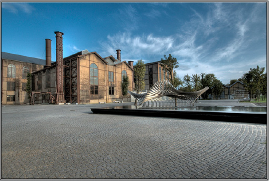
it is a museum building; the building, known as Silahtaraga Power
Plant of the period, meets the electricity needs of Istanbul (Figure2).
With the planned decovil line, it is aimed to evaluate the coal
reserve on the Black Sea coast and to transport it to the Silahtaraga
Power Plant without the need for sea transportation. In this way,
the solution to the energy problem of Istanbul will be produced.
Although the existence of the coal reserves of Agacli, Ciftalan region
on the Black Sea coast has been known since the Byzantine Period,
no studies have been conducted to make the reserve available
for use. After the preliminary investigation, it is determined that
the desired yield can be obtained by mixing the lignite coal in the
region with Zonguldak hard coal, and it is decided to use the coal in
the region and construction of the decovil line is started. The entire
installation works are photographed by Hasan Mukadder Dolen,
the railway regiment officer of the period.
Hasan Mukadder Dolen’s photo collection was left to his
grandson Emre Dolen after his death in 1975. It is known that many
photographs and information about the historical railway have
survived through this channel. Following the first line completed
in 1915, a second line was built in Ciftalan in 1916. Railway rails
and locomotives produced by Germany’s decovil line, with many
stations, vehicles and employees is important in terms of energy
logistics of the period. It is mentioned in the historical documents
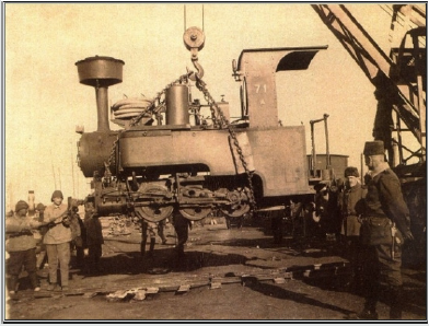
that the rails and locomotives transported from Germany to the
Ayestefanos Railway Regiment warehouses in Yesilkoy by the
Danube River were later brought to Eyup, Silahtaraga by ships
(Figure3).
The first line starts from Silahtaraga and reaches Agacli village
after Kagithane stream; the other line runs through the Belgrade
forests to the village of Ciftalan. The light rail line that reached the
Black Sea coast from Kagithane, which is the famous promenade
of the period, undertook an important duty in coal transportation
during the years it was established, but was forgotten by being out
of use in time.
The line was transferred to the Ministry of Commerce in
1922 and to the Ministry of Economy after the proclamation of
the Republic [4]. Although traces of the line disappeared in the
region after 1956, the rails remained largely underground and
in many regions the rails were removed. It is known that one
of the locomotives is currently located in the Celtek coal mine
depot of the Special Provincial Administration of Amasya. In the
photogrammetry study for the protection of cultural heritage, CAD
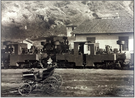
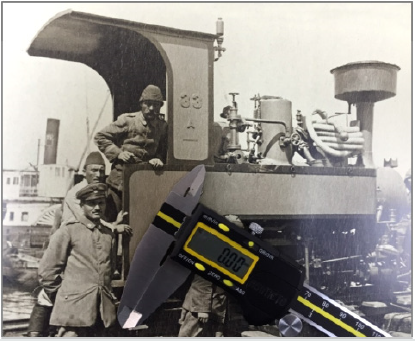
model will be created by using original photographs of locomotives
known as Zwilling Heeres Feldbahn (Double Military Decovil)
produced in Munich in 1890 by Krauss Werkshof [1] (Figures 4 &
5). The first prototype of the model produced with SLS (Selective
Laser Sintering) one of today’s 3d print technologies, will be used
for silicon mould technique in mass production.
Literature on Photogrammetry
In this part of the article, the photogrammetry study carried
out with measurements taken from photographs of locomotives
used in historical railway will be shared. In this context, sharing of
literature knowledge about photogrammetry and its usage areas
and then modelling study were included in the study. Visual analysis
techniques are used in many scientific research areas. In the fields
of anthropology and sociology, from the use of photographs of past
periods [7] to airborne imaging technologies[8]; visual analysis
techniques in different scientific fields from ecology, geography to
medical science [9], are basically based on the use of photography
as a source of information. Photographs used as data in the social
field allow interpretations, social-cultural determinations and
visual analysis of the time of the photograph [10]; in technical
fields, it can also be used as a digital data source.
The use of photography for numerical data acquisition will be
explained within the framework of photogrammetry concept. The
word, which consists of a combination of ancient Greek “photos”
(light), “grama” (drawing) and “metron” (measurement), means
measuring with the help of pictures. Photogrammetry, which
is used only in mapping, has been used in different areas in the
following years. Basically, the photographic analysis to determine
the shape, size and position of an object is called photogrammetry
[11]. Photogrammetry is divided into three main sections
(topographic photogrammetry, interpretation photogrammetry,
special purpose photogrammetry) according to the application
areas. Photogrammetry used in the fields of architecture, dentistry
and archaeology is included in this third group [12].
In recent years, many studies have been done to document
the cultural heritage with photogrammetric methods [13],
photogrammetry has been used extensively in histor ical works
documentation and model formation processes [12]. In such
studies, the measurements taken on the photos allow the creation
of the 3-D model of the historical work on the computer with digital
photogrammetric techniques [14]. While the measurement process
is carried out with the points and lines determined by the software,
different methods can be used. In our study, the CAD model, which
is designed with the measurements with calliper and ruler from old
photographs, will be discussed within the scope of special-purpose
photogrammetry.
Modelling Process
In this part of our study, we will discuss the modelling process
created by taking measurements from the historical photographs
of the railway line locomotive of Kağithane. In the modelling study,
the locomotive CAD model was created in CATIA V5. The modelling;
cabin, nose, mechanical parts and rails, including a total of 4 body
consists of (Figure 7).
Part design tools are used in the modelling. The modelling
of the locomotive as 4 bodies is taken into consideration for the
production criteria for the silicone mould to be needed during
mass production. In this sense, the model has been modelled and
divided into pieces so as to enable post-production assembly. In
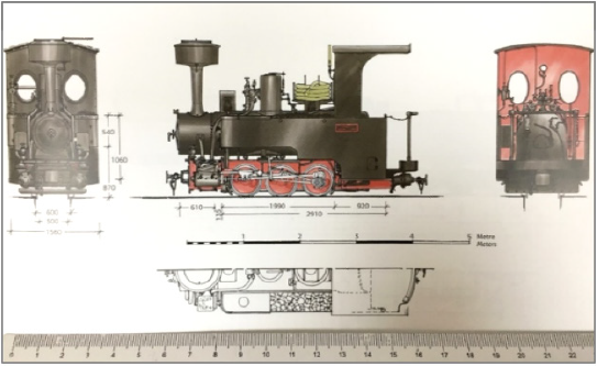
the modelling study, first the technical drawings (Figure 6) made
by Alan Prior were used for general information about the model;
in the detail drawings, black and white photographs taken from
different angles were used. After the results of modelling, some
forms are very detailed for the casting process and line softening is
performed according to the model casting process (Figure 7).
Data Transfer to 3d Printing System After Modelling
(STL File, Quality Problems) STL (Stereolithography) data is
needed for additive manufacturing of the model. The CAD data
generated for this reason is exported in the STL format in the
CATIA software. In this process, STL mesh quality is important
for the surface quality of the model to be produced. The quality
of the prototype to be produced with SLS will affect the quality of
the silicone mould from this prototype. The quality problems in
the STL data are related to the number of mesh on the surface and
the settings of the CATIA display and the necessary arrangement
is made as follows: First, the screen settings are set in the ”tools“ -
”options” – “performance” section in the top menu of the CATIA Part
Design module. In this section, the 3D Accuracy and 2D Accuracy
“fixed” values are revised to “0.01”. The value 0.01 remains constant
until changed again.
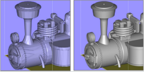
The next editing is done in the CATIA STL Rapid Prototyping
module. In the “tesselation” command, with “sag” value, 0.001mm
and “grouped” option preference, the mesh quality of each part is
determined (Figure 8: on the effect of mesh quality adjustment on
surface quality in STL data).
Model Production Process
The technique used in the prototype production is SLS (Selective
Laser Sintering) and the material used is PA 2200 (polyamide). If we
need to give basic information about SLS production system: The
SLS technique is made by sintering micron-size polymer powder
in layers, using laser power. In 1986, Carl Deckard, a student
at the University of Texas, developed this method of powdered
material, which he called PGLSS (Part Generation by Layer wise
Selective Sintering). Later on, this production technique called SLS,
(with the description text: computer-aided laser apparatus which
sequentially sinters a plurality of powder layers to build the desired
part in a layer-by-layer fashion) is patented on October 1986 [15].
The method of SLS production is as follows:
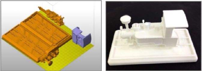
Firstly, files saved in STL format are opened in Netfabb software
and settled in the production area. (Figure5). All parts are sliced at
intervals of 0.1 mm (100 microns) after placement. Then the file
sliced into 100 microns is saved in SLI format. Although there are
60 microns slicing options within the system, 100 microns will be
sufficient for the desired quality. Then the process will continue in
the EOS PSW software. After the material preference and parameter
selection in EOS PSW software, the file will be transferred to the
production bench. The material preference is selected as PA2200
and the layer thickness is 100 microns. The production parameter
is then determined. After the prototype production to be performed
in EOS P110 (Figure 9), silicone moulding will be carried out for
mass production.
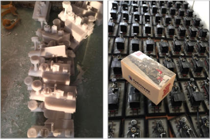
The first prototype produced with PA 2200 material, is used to
form the silicone mould. After that, the model which is replicated
in the manufacturer company by casting process from polyester
material is painted with handwork and the final product is obtained
(Figure 10). In classical applications, the silicone mould is taken
from the prototype modelled by the sculptor and polyester casting
process is performed. In the prototype production subject to our
study, the process was completed by using digital technologies and
methods. In the study, modelling was performed in parametric cad
software, enabling the revisions needed in the process to be made
quickly.

No comments:
Post a Comment
Note: only a member of this blog may post a comment.