Lupine Publishers | Current Investigations in Agriculture and Current Research
Abstract
The article concerns the problem of determining the optimal depth of flowing well. It suggests that the increase of the well yield subject to the elongation of water intake part occurs rather irregularly, and its pattern is more likely to be hyperbolic. Based on the detail analysis of the case it is not recommended to situate the water intake of the well along the all thickness of the aquifer since there comes a time point when the capital inputs made for further elongation of the water intake are not compensated by the corresponding yield increase. As first approach we suggest that the length of the water intake filter should be accepted of (0,5 … 0,6) size of the aquifer part. For precise determination of optimal length of the water intake, thus for the entire well, it is suggested to build the curve of capital unit costs by formula (11), determine the coordinates of points of its minimum and, following this, as a final result – appropriate for it length of water intake.
Keywords: Flowing well; Yields; Hydraulic resistance; Water intake filter; Optimal depth; Capital costs
Introduction
The highly confined aquifer of the Ararat valley, which in general is a source of drinking water supplied to the Republic settlements, is situated at a great depth. Huge capital inputs are required for building here each water intake flowing well. The costs that depend on the drilling depth, in case the rest conditions are equal, increase in direct ratio. At that, in case of great depths (dipper than 50 m) the cost of drilling 1 linear meter rises 1,63 times. Considering this, it is important to develop a method of determining the optimal depth for embedding the well.
Materials and Methods
To minimize the construction costs of flowing well it is necessary to reduce the drilling depth as much as possible. It is clear that reduction of depth will be done only within the limits of the aquifer, by minimizing the length of the water intake part. But the reduction of the latter causes the increase of imperfection coefficient of the well and this in its turn leads to a significant yield drop. In case of pump-operating vertical well the size of depth reduction can be minimized if the piezometric head drop is increased, whereas in case of flowing well it is impossible since the water intake here is mainly performed at the expense of inner elastic compression energy some part of which actually will be spent on overcoming the generated additional hydraulic resistances. From the theory of groundwater movement, we know that the functional relation of water intake filter length and well imperfection coefficient is hyperbolic, and when the length of the water intake reaches to the half of aquifer thickness its inclination abruptly changes, and it asymptotically gets close to the horizontal axis [1-3]. That is why during the constant elongation of water intake part the yield at first increases more abruptly, but further its growth decreases. There comes a moment when the further elongation of the water intake does not cause such considerable yield increase which can compensate additional capital expenses done for this elongation.
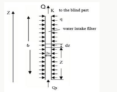
The essence of the problem is to determine such depth of flowing well in case of which the capital expenses done for producing one-unit yield will be the least. Let us consider the solution of the problem at first approach by assuming that the well construction costs, dependent on its depth, increase in a way of direct linear relation. It should be mentioned that in case of flowing well we certainly must consider also the energy longitudinal losses in the water intake filter. Let us calculate these losses considering the water intake as a pipe with equally distributed affluent with q intensity [4-6]. For the pressure losses on length dz in cross section z, by the Darcy-Weisbach equation we can write:

where QB- affluent of subterranean waters through the well bottom, λ-Darcy’s coefficient, ro- radius of the well.
Herein, with some approximation, we accept that λ along the entire length of the water intake filter does not change and has the same value as it is in the blind part of the well (Figure 1).
By integrating equation [1] along the entire length of water intake, we get:

based on which

Usually there is a settler built at the end of the water intake of the well at the availability of which we get QB=0. In this case equation (3) will get the following look:

Formula (4) indicates that pressure losses at variable yield make up 0,33 part of losses on the same length with constant Q yield. In case there is no settler, partially, in the fractured rocks, ignoring QB does not lead to significant errors. It is justified by considering that if the water intake has such length at which we should also take into account the pressure losses, thus, as a rule, the total affluent along the length certainly exceeds that of the bottom. For determining the yield of a single operating flowing well N. Melikyan suggested the following formula [7-10]:

where k is aquifer filtration coefficient, m is bed thickness, Hp is positive pressure of the wellhead,

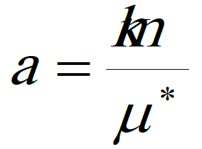
is transmissivity coefficient of this bed, μ*-ն elastic yield coefficient, t is the time for which the well yield is determined, ξ=ξ1 +ξ2 is the general imperfection coefficient of the well, ξ1 and ξ2 are imperfection coefficients according to the aquifer passing pattern and size, respectively; η is total inner hydraulic resistance:

where ℐ and ℐF are respectively the lengths of blind part of the well and of the water intake, λ – longitudinal resistance coefficient of hydraulic friction which for simplicity is accepted the same in both parts.
To solve the problem let us consider variation of Q, when in equations [5] and [6] the only variables are ℐF and ξ2. In this case from equation [5] we get:

At that ξ2 relation from ℐF can be accepted according to VM Shestakov [11-14] in the following way:

where ε coefficient is determined in accordance with the following table: Approximating (8) the data in Table 1, we get

To determine the capital construction costs of the whole well we use the following equation:

where Kօ is the cost of one linear meter of the well which is chosen according to the corresponding standards in accordance with the soil types. The capital unit cost of the yield produced by the flowing well will be as follows:

Results and Discussion
We can determine economically efficient depth of the flowing well on the basis of extremum condition of F(ℐF) function:

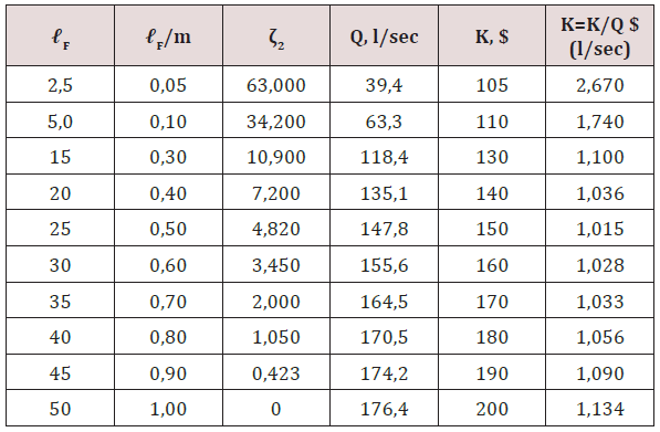
As we see in formula (11) (Table 2), the analytical solution of equation (12) depends on considerable mathematical complexities, though they can be circumvented if the problem is solved graphically. Let us elucidate it by the example of a flowing well of the Ararat valley, the aquifer hydrogeological characteristic of which is as follows: k = 40 m/day, m = 50 n, HB = 20 m, а = 2·104 m2/ day, well radius ro = 0,1 m, the aquifer roof is situated at 50 m depth (ℐ= 50 m) from the earth surface. For clarity let us assume that the coefficient of longitudinal friction resistance at the entire length of the well, including also the water intake part, remains constant, and in this case λ = 0,012, let us also accept that the well in accordance with the aquifer passing pattern is perfect (ζ1= 0).
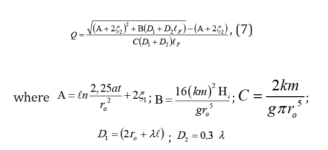
By the values of the aquifer and well parameters, the formula (7) constants will be as follows:
A=19,92; B=1749,9 1/m; C=1,734 · 10–3 1/m; D1 =0,8 m, D2=3,96·10-3.
Inserting these values in formula (7), we have:

By giving to ℓF different values in the interval from 0 to 50 m, let
us calculate ζ2 by corresponding to them formula (9), Q - by formula
(5), K - by formula (10) and  - by formula (11). Based on the data
presented in columns 1, 3, 4 and 6 of Table the graphs of ζ2=ƒ1(ℓF),
Q= ƒ2(ℓF) and

dependences are built and suggested in Figure 2. As we see in the graph, function ƒ3(ℓF) has one extremum point and it is the minimal. The value of ℓF corresponding to this point will be the economically optimal length of the well water intake. In the studied example it makes up ℓF = 26 m, thus the total length of the well will be 76 m.
Conclusion
- The functional relation of the flowing well yield and its water intake length has approximately hyperbolic view and after some values of the water intake length the capital inputs done for its elongation are not compensated by the corresponding yield increase.
- Drilling of flowing well along the entire thickness of the aquifer is not economically efficient.
- The length of the well water intake at first approach is suggested to be assumed 55 - 65 % of the aquifer size.
- In case of any proximate existing initial data the water intake optimal length can be defined if the curve of capital unit costs will be built up by formula (11) and its minimum point will be defined.


No comments:
Post a Comment
Note: only a member of this blog may post a comment.