Lupine Publishers| Advances in Robotics & Mechanical Engineering (ARME)
Abstract
Recent investigations in gyroscope effects have demonstrated that their origin has more complex nature that represented in known publications. On a gyroscope are acting simultaneously and interdependently eight inertial torques around two axes. These torques are generated by the centrifugal, common inertial and Coriolis forces as well as the change in the angular momentum of the masses of the spinning rotor. The action of these forces manifests the inertial resistance and precession torques on any rotating objects. New mathematical models for the inertial torques acting on the spinning rotor demonstrate fundamentally different approaches for solving of gyroscope problems in engineering. This is the very important result because the stubborn tendency in engineering is expressed by the increasing of a velocity of rotating objects. The numerous designs of the movable machines and mechanisms contain spinning components like turbines, rotors, discs and others lead to the proportional increase of the magnitudes of inertial forces that are forming their processes of work. This work considers the inertial torques acting on the on a rotor of an electric railway carriage rounding a curve, which expresses the gyroscopic effects.
Keywords: Gyroscope theory; Inertial torques; Spinning rotor
Nomenclature
i. m - Mass of the rotor
ii. g - Gravity acceleration
iii. I - Index for axis ox or oy
iv. J - Mass moment of inertia of the rotor
v. L - Radius of rolling the carriage along the curvilinear path
vi. R - Radius of the rotor
vii. Tam.i, Tcti, Tcr.i, Tin.i - Torque generated by the change in the angular momentum, centrifugal, Coriolis and common inertial forces respectively, and acting around axis i
vii. Tr.i, Tpi - Resistance and precession torque respectively acting around axis i
ix. ω - Angular velocity of the rotor
x. ω i - Angular velocity of precession around axis i
Introduction
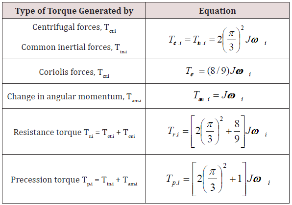
Most of the textbooks of machine dynamics and books that dedicated to gyroscope theory content the typical examples with solving of gyroscope effects [1-3]. However, the practice demonstrates that the known mathematical models for acting forces on the rotating objects do not match their actual forces and motions [4,5]. Recent investigations in the physical principles of gyroscopic motions have presented the new mathematical models of forces acting on a gyroscope [6-8]. The action of the external load on a rotating object generates several inertial resistance and precession torques based on the action of the rotating mass elements of the rotating object. Resistance torque is generated by the action of the centrifugal and Coriolis forces of the rotating object’s mass elements. The precession torque is generated by the action of the common inertial forces of the rotating object’s mass elements and by the change in the angular momentum. These resistance and precession torques act simultaneously and interdependently and strictly perpendicular to each other around their axes. Equations of inertial torques generated by the rotating mass of the rotor are shown in (Table 1) [6].
Table 1 contains the following symbols: J = mR2/2 is the rotor’s mass moment of inertia around the spinning axle; 𝓂 is the mass of the rotor; R is the external radius of the rotor; ωi is the angular velocity of the precession of a spinning rotor around axis i and ω is the angular velocity of a rotor. The following analysis of the actions of several torques and motions around two axes has used the system of subscripts signs. All components of the equations are marked by subscript signs that indicate the axis of action. For example, Tr.x is the resistance torque acting around axis ox, ωy is the angular velocity of precession around axis oy, etc. A different type of the rotating objects as a wheel, discs, etc., possess gyroscopic properties. The electric railway carriage rounding a curve is considered as a flat motion and its electric rotor possess inherent the gyroscopic effects. This work presents the mathematical model for the forces acting on the bearings of the rotor for the electric railway carriage rounding a curve.
Methods
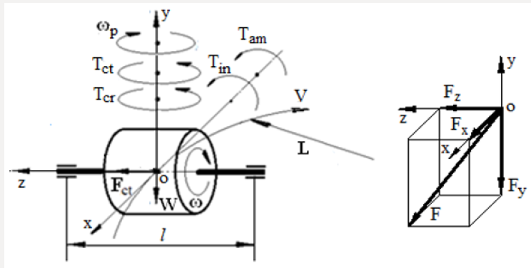
The electric railway carriage rounding a curve and its electric motor is loaded by inertial forces that manifest gyroscopic effects. The curvilinear motion of the of the electric motor demonstrates the gyroscope effects of the spinning rotor, which presented by the action of centrifugal, common inertial, and Coriolis forces and the rate change of the angular momentum. The action of these forces presents the additional load on the bearings of the electric rotor. The study of the action of the inertial forces on the rotor is assumed that electric railway carriage rolls with the constant angular velocity. Figure 1 represents the spinning electric rotor and loads generated by the inertial forces of its mass and weight at the system of coordinate Σoxyz. According to the new mathematical models for the inertial torques acting on the spinning rotor (Table 1), the curvilinear turn of the rotor produces the several torques generated by the rotor’s mass and the weight. The action of these loads produces the reactive forces on the bearings of the rotor’s supports. The inertial torques and other loads acting on the spinning rotor are represented by the following components:
a) The resistance torques based on the action of the centrifugal Tctx and Coriolis forces Tcrx acting around axis ox.
b) The precession torques based on the action of the change in the angular momentum Tamx of the rotor and the common inertial forces Tinx acting around axis oy.
c) The curvilinear turn of the rotor on railway generates the centrifugal forces acting bearings of the electric rotor.
d) The weight of the rotor generates the reactive forces on the supports.
Figure 1 demonstrates the action of the inertial torques and the weight on the spinning rotor that moves on curvilinear rail way track. The turn of the rotor around axis oy generates the resistance and precession torques acting around axes ox and oy respectively. These torques are expressed by one equation but with own symbols that represented in (Table 1). The centrifugal force generated by the of the centre-mass of the rotor at the time of the curvilinear motion of the carriage is defined by the following equation:

where Fct.my is the centrifugal force generated by the of the centre-mass of the rotor; 𝓂 is the rotor mass; V is the tangential velocity of the carriage; L is the radius of the carriage rolling on the rail track; ωp is the angular velocity of the carriage on the curvilinear rail track. The rotor’s weight produces the load forces on the rotor’s supports that is defined by the following equation:

where FWy is the load force generated by the of the centre-mass of the rotor acting on the radial-thrust bearings; W is the rotor’s weight; l is the distance between the bearing and the centre-mass of the rotor; g is the gravity acceleration; other parameters are as specified above. The total forces acting on the bearing of the rotor along axis oy and ox are represented by the following equations:

where Fy and Fx are the total forces acting on the bearing of the rotor along axes oy an ox respectively.
Substituting expressions of the inertial torques generated by the mass of the rotor into Eqs. (3) and (4) and transformation yields the following equations:

The combined load acting on the most loaded bearing of the rotor is defined by the following equation (Figure 1):

where all parameters are as specified above.
The combined load (Eq. (7)) should be used for defining the appropriate radial-thrust bearing of the spinning rotor.
Working Example
An electric carriage is rolling on the curvilinear rail track of radius 300m with the linear velocity of 90.0 km/h. The motor used for traction has a rotor of mass 600kg and the radius of gyration 300mm. The motor shaft is parallel to the axes of the carriage’s running wheels. The rotor is supported in bearings 750mm apart symmetrically and rotates of 160.0 rad/s (Figure 1). Determine the combined force generated by the inertial forces of the rotor and its weight acting on the most loaded bearing.
For solution is defined as the following:
a) The angular velocity of precession:
ωp= V/L= (90000/3600)/300 = 0.083333 rad/s
where V is the linear velocity of the carriage, L is the radius of the rail curve.
b) The rotor’s mass moment of inertia
J = mr2 = 600×0.32 = 54.0 kgm2
where 𝓂 is the rotor’s electric motor mass, r is the radius of gyration.
c) The rotor’s angular velocity
ω = 160.0 rad/s
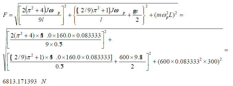
d) The combined force acting on the bearing is defined by the substituting defined above parameters into Eq. (7)

Analysis of obtained result demonstrates that inertial forces acting on the bearing is almost more than two times bigger than the weight of the rotor.
Results and Discussion
New analytical approach to the inertial forces acting on the gyroscopic devices enables developing the equations for the torques and motions of any rotating objects moving in the space. The mathematical model derived for the total force acting on the rotor’s bearing of the electric motor for the carriage rolling on the curvilinear rail track is based on the action of the centrifugal, common inertial and Coriolis forces, as well as the change in the angular momentum and the weight of the rotor. The new analytical approach to the gyroscope problems demonstrates and explains the physical principles of acting forces on a spinning rotor. The mathematical model for the force acting on the bearing of the rotor of electric motor confirms the manifestation of the gyroscopic effects. This model should be used for computing the load on the bearing of the rotor for the movable electric motors and represents a good example for the educational process.
Conclusion
In the area of publications of gyroscopic effects, the forces acting on the rotating objects is one of the most complex and intricate in terms of analytical solutions. The new mathematical models for gyroscopic torques consider the simultaneous and interdependent action of several inertial forces generated by the rotating mass elements and centre mass of the spinning objects. As a practical application, these new physical principles for gyroscopic effects were used for modelling of the forces acting on the spinning rotor of the electric motor. This mathematical model is distinguishing from those in well-known publications, which tend to have complex numerical modelling that does not interpret the origin of gyroscopic effects. The application of new mathematical models for acting forces on the spinning rotor effectively and clearly demonstrates physical principles of loads.
Read More About Lupine Publishers Advances in Robotics & Mechanical Engineering (ARME) Please Click on Below Link: https://robotics-engineering-lupine-journal.blogspot.com/


No comments:
Post a Comment
Note: only a member of this blog may post a comment.