Lupine Publishers| Journal of Civil Engineering and its Architecture
Introduction
A Fundamental civil engineering knowledge is the ability to understand, explain and calculate deformations of/in civil structures. New civil engineers acquire this knowledge at universities in material science, engineering mechanics and introduction to structural engineering modules. Structural deformations can be calculated when knowing material properties, geometry and boundary conditions of a structure and loads that are applied on/to it. Inverse engineering can be employed if deformations of a structure are known, but some other parameters are not known. Theoretical formulae are then tested using laboratory test beds, usually beams. Laboratory technicians are responsible for the acquisition of deformation measurements of laboratory tests. Their time is often limited and so is the number of available measurement collection devices such as dial gauges and strain gauges. If devices that do not log measured deformations are employed, information of structural deformations or response might be lost or readings might not be collected at required intervals. However, all laboratories do not offer luxury of sensors that are available at hand and technicians, which would have time to install sensorsand collect data when needed, especially if this as to be done with a short period of notice. This paper introduces a low-cost vision-based system for deformation estimations of laboratory structures.
Significant research is done in the image processing and photogrammetry fields, which is reviewed in recently published paper [1]. Ho et al. [2] demonstrated that two camcorders when used simultaneously can capture displacements of civil structures. Ye at el. [3] employed high-resolution industrial digital cameras with extended-range zoom lenses to collect dynamic movements of long- span bridges and derived structural displacements from collected images. In above examples, camcorders or high-resolution cameras were employed. This study shows that mobile phone cameras can be used to do the above. DefoMonit- software introduced in this paper and developed at Nottingham Trent University (NTU) [4], can analyse consecutively collected images of structures subjected to loadings and estimate structural deformations. DefoMonit, in contrast to proprietary software, is free for students and academics. The next sections provide general introduction to the vision-based system and a laboratory case study.
Methodology
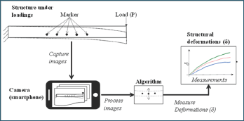
Figure 1: A schematic representation of condition assessment of a structure under loadings using a low cost vision-based measurement collection system with a smart phone camera.

Figure 1 presents a proposed system for estimating deformations such as deflections in laboratory test-beds. A selected test-bed is a cantilever beam subjected to loadings. Markers or points of interest are drawn on the surface of the beam. Images are captured with a phone camera while the load is applied to the beam. When analysing collected images with DeforMonit, the location of the markers is tracked, and structural deformations are estimated.
A laboratory structure subjected to loadings
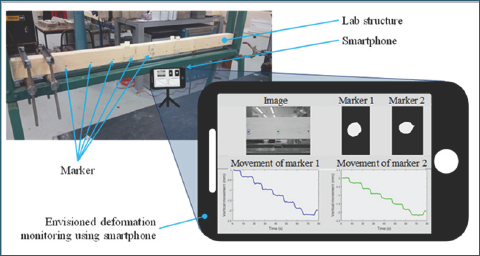
Figure 2: Envisioned set-up of the vision-based system using a phone to collect and DeforMonit to analyse images for deformation estimation of a cantilever at the lab in (NTU).a.

An illustration of the proposed system using a phone for deformation monitoring of a cantilever beam is shown (see Figure 2). Markers are drawn on the face of the beam. A phone is placed at a preferred distance from the laboratory structure. Setting the correct distance, at which images are taken, has a direct impact on the resolution of images and calculated structural deformations. Understanding of structures is required to provisionally estimate expected movement of the laboratory structure. The collected images are analysed using DeforMonit, and time series of estimated deformations are generated.
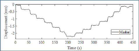
Figure 3: Time series of vertical movements of a selected marker on the timber beam.

Consider the timber cantilever shown in Figure 2. The cantilever is 900mm long, 45mm wide and 70mm deep. A load is applied manually at its right end using 5N load step. When the applied load reaches 35N, it is removed using 5N steps. Samsung A3 phone is deployed to capture images of the cantilever under loadings. The phone is placed 800mm away from the cantilever capturing its entire length. The movement of a marker at its far right end is tracked and plotted in Figure 3.
Summary and Conclusion
This synopsis introduces DefoMonit, a freeware for image analyses of structures subjected to loadings for accurate estimations of structural deformations. The accuracy of estimated deformations using DeforMonit is validated on laboratory and full-scale structures [4]. Students at NTU use DeforMonit in their final year project. In this paper, an example showing deformations of a cantilever beam subjected to manually applied loads is demonstrated in Figure 3.
Read More About Lupine Publishers Journal of Civil Engineering and its Architecture Please Click on Below Link: https://lupinepublishers-civilengineering.blogspot.com/

No comments:
Post a Comment
Note: only a member of this blog may post a comment.