Lupine Publishers- Environmental and Soil Science
Abstract
Geophysical and Geotechnical investigations were carried out on the proposed New Oil Mill at Wilmar Calaro Oil Palm Estate in Awi- Akamkpa of Cross River State. Five borings were carried out at the depths of 42.3 m and 3 m at intervals of 1m and 4.7 m respectively. The samples were taken to the laboratory for Sieve analysis, compaction test, California Bearing ratio test, plasticity index, maximum dry density, unconfined triaxial test, and shrinkage test to determine the bearing capacity of the soil. The results revealed that the subsurface displayed good bearing capacities characteristic of (1.5m and 467.20KN/m2). Settlement predictions based on a loading of 100KN/m2 indicated a settlement of 1.68 mm. Hence, the subsurface is adjudged to be suitable for the proposed construction with the expected superstructure. Seismic refraction was also carried out in the locations the geotechnical borings were made using a 12channel seismograph (Teraloc) model DPU 411 to determine the bearing capacity of the subsurface. The five selected locations that were investigated shows that the hammer source penetrated the first three layers of the earth. A software seislmager was used to analyze the data. The range of Velocities for the first three layers were 276 m/s to 1148 m/s, 544 m/s to 2270 m/s and 1134 m/s to 5368 m/s, their depths to bottom were 1. 7 m to 8.1 m and 7.2 m to 13.5 m and the shear modulus (μ) of 0.97 x 10⁸N/m2, young modules (E) of 2.06 x 10⁸N/m2 to 331 x 108N/m2, Lame’s constant (λ) of 0.14 x 10⁸N/m2 to 927 x 108N/m2 and Poisson ratio (σ) of 0.01 to 0.3 were calculated, the soil identified in the survey area were mainly sand, clay, shale, gravel, and granite. Seismic refraction and geotechnical results show a good agreement that the soil is well consolidated, and it is suitable for the expected deep foundation building.
Introduction
A foundation is a part of an engineering structure that transmits the structures forces into the soil that supports it, the shape, depth, and materials of the foundation design that depend on many factors including the structural loads, the existing ground conditions, and local material availability. The Wilmar is an oil palm producing company that intends to build an oil mill with a deeply seated foundation. A soil test is needed for the determination of its capacity to bear the load and it’s important to determine relevant engineering characteristics of the sub-soil, soil bearing capacity and as well as advance recommendations on the soil bearing capacity. However, proper design of building foundation requires the knowledge of the external loads transmitted by the building, superstructure, the local code requirements, the nature and composition of different types of soil at the site, and the behavior of the stress-related deformability of soils supporting the foundation system. All civil engineering structures impose a loading on the underlying soil or rock. The lowest part of the structure, usually lying below the ground level, which transmits the load to the supporting soil/rock strata, is known as a foundation. The ability of the underlying soil to bear the load of the foundation without overstressing the soil in terms of either shear failure or excessive settlement is termed as bearing capacity of the soil. This is often termed as bearing capacity of the foundation. The bearing capacity of a soil depends mainly on the types of foundation encountered by the soil. Foundations of structures are basically of two types; shallow and deep. The classification indicates the depth of foundation installation and the depth of the soil strata providing most of the support.
Similarly, the general geological conditions of the site must be ascertained. The use of soil test before erecting the structure cannot be overemphasized because of the prevalent cases of building collapses across the South-South region of Nigeria where the project site is situated. To assuage this limitation inaccessibility, this study employed the traditional geotechnical soil engineering method and a non-invasive geophysical seismic refraction method to study the bearing capacity of the area under consideration, this articulates the main objective of this research. The pattern and manner at which structural buildings are collapsing in Nigeria, pose a serious threat to structural engineers, building industry, government, estate developers, building consultants and other relevant stakeholders in the building industry, as well as landlords and tenants and it called for proper a geotechnical soil investigation [1]. The frequent occurrence of building collapse in Nigeria requires an immediate interception to substandard materials, as substandard materials have been noted of being the major cause of worldwide building collapse [2-4].
Review of Some Literature
The behavior of seismic waves traveling in rocks has been a subject of extensive theoretical and experimental investigations since the beginning of the eighteenth century, such researches have yielded results whose workability in most cases is still being tested [5]. Useful formulas exist for characterizing the elastic nature of the earth, these relations have to do with stress and strain and have been documented in most textbooks [6,7]. In the building/construction industry, elastic behavior of rocks and their characteristics have been used to test the bearing capacity of soils and foundation materials before construction work commences, in view of the heterogeneous nature of soils both laterally and vertically it is not advisable to extrapolate results beyond the study area. The Elastic parameters utilized in the assessment of the bearing strength of foundation materials in this study are Bulk modules (K), Shear modulus (μ), Poisson ratio (σ), Young modulus (E) and Lame constant (λ), the relationship with measurable parameters like S-wave velocity, P-wave velocity, and rock density is expressed in equations documented by Skempton AW et al. [6]. A soil shear failure can result in excessive building distortion and even collapse. Excessive settlements can result in structural damage to a building frame nuisance such as sticking doors and windows, cracks in tile and plaster, and excessive wear or equipment failure from misalignment resulting from foundation settlements. It is necessary to investigate both base shear resistance ultimate bearing capacity and settlements for any structure. In many cases, settlement criteria will control the allowable bearing capacity. Except for occasional happy coincidences, soil settlement computations are only best estimates of the deformation to expect when a load is applied. The components of the settlement of a foundation are the immediate settlement, Consolidation Settlement, and Secondary compression or creep.
ΔH = ΔHi + U ΔHc + ΔHs 1
Where: ΔH = total settlement,
ΔHc = consolidation settlement,
ΔH = secondary compression,
U = average degree of consolidation. Generally, the final settlement of a foundation is of interest and U is considered equal to 1 (i.e. 100% consolidation).
Immediate Settlement
The immediate settlement concerns the initial pressure on the soil under and surrounding the foundation. It is “immediate” because it occurs during and right after construction. It has nothing to do with water displacement but is merely caused by the weight of the structure. In terms of building foundations, the immediate settlement is relatively easy to predict and measure. In many cases, given the nature of the soil, foundations are constructed with the ability to withstand a certain amount of shift without damage. Damage usually occurs only in the long term, as the shift slowly continues over time. Immediate settlement takes place as the load is applied or within a time period of about 7 days. Predominates in cohesionless soils and unsaturated clay. Immediate settlement analysis is used for all fine-grained soils including silts and clays with a degree of saturation < 90% and for all coarse-grained soils with a large coefficient of permeability (say above 10.2 m/s).
Consolidation Settlement (ΔHc )
Consolidation settlement is distinguished from immediate settlement both by the duration of the settlement and by displacement of water. Consolidation is the more worrisome form of a settlement because it is difficult to predict over months or years. Consolidation settlement is the settling of a foundation, over time, due to pressure exerted by the structure and squeezes out the water content of the soil, thus compressing it. Expulsion of moisture from the soil usually is a long-term process. Consolidation settlements are time-dependent and take months to years to develop. The lean is caused by consolidation settlement being greater on one side. This, however, is an extreme case. The principal settlements for most projects occur in 3 to 10 years. Dominates in saturated/nearly saturated fine-grained soils where consolidation theory applies.
Secondary Settlement/Creep (dhc)
Consolidation settlement has two components, primary and secondary. The former deals explicitly with the settlement caused by soil moisture displacement and the latter deals with the elastic settlement after all movable water has been squeezed out of the soil. Primary consolidation is the most significant and potentially harmful of the two. Primary consolidation takes quite a bit of time, from weeks to years. Secondary consolidation is the quicker result of primary consolidation. Once primary has been completed, and all movable water has been moved, secondary kicks in. Secondary consolidation occurs immediately after the primary and takes far less time to complete. After secondary consolidation is complete, the structure remains in its permanent position. As a result, many builders advise residents in new homes to avoid repairing any settlement damage until secondary consolidation is complete, which is normally after two years at most. Occurs under constant effective stress due to continuous rearrangement of clay particles into a more stable configuration. It predominates in highly plastic clays and organic clays. Accordingly, [6] he suggested the following permissible settlements for sand and clay as follows; sand maximum total settlement 40 mm for isolated footing (40 - 65 mm) for rafts. Maximum differential settlement 25 mm between adjacent columns and clays Maximum total settlement 65 mm for isolated footing (65 - 100 mm) for rafts. Maximum differential settlement 40 mm between adjacent columns. The differential settlement may also be evaluated in terms of the angular distortion given by:
ΔHdiff = Δ / L 2
Where = relative settlement between the two points and L = Horizontal distance between the two points.
Deep Foundations
The shallow foundations may not be economical or even possible when the soil bearing capacity near the surface is too low. In such a situation, deep foundations are used to transfer loads to a stronger layer, which may be located at a significant depth below the ground surface. The load is transferred through skin friction and end bearing.
Materials and Methods
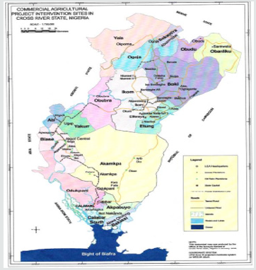
This research is a pioneering work in the study area aimed at determining the bearing strength of the soils within the Calaro Oil Palm Estate. Geologically, the site is underlain by crustal sediments, which in this area is dominated by sandy gravelly sediments belonging to the Albian Asu River Group (ARG). The general geology of the area essentially reflects the pattern of crystalline basement rocks which consist basically of magmatic and granitic gneiss and schist with pegmatic intrusions in some locations. There is a close proximity of the basement to the surface, this and other tectonic activities over time results in synclines and anticlines surfaces; hence the area is not fairly flat. The deposit in the area comprises of sandy gravels with a mild presence of clays. The near-surface clays are not subjected to desiccation, see the map of the study area (Figure 1).
Soil Boring
Two borings each 42.7 m deep were made with the aid of a drilling rig, soil samples were collected at 4.7 m intervals. Another three borings each 3 m deep were also made. In this bore, soil samples were collected at 1 m intervals. An excavator was used to remove the topsoil up to a depth of 3 m after which a cylindrical cutter was used to collect undisturbed samples in two locations very close to the borings. The samples were transported to the laboratory for sieve analysis, compaction test, California Bearing Ratio (CBR), plasticity index, maximum dry density, shrinkage test, unconfined triaxial test. Bearing capacity was determined experimentally in the laboratory in line with ASTM STP 4. Hydraulic powered static cone penetrometer of 2.5-tonne capacity was used for the sounding. Bergmann type mechanical cone friction jacket was used for the test. The cone in its retraction state is forced into the sample a distance of 50 cm by the application of force to the outer sounding tubes. The cone is then pushed out a distance of 4 cm by the application of force to the inner rods only and the magnitude of the force required to achieve this is measured in the pressure gauges and recorded (this is the resistance). Again, the cone is pushed down further 3 cm with the friction jacket going down with it. The cone resistance together with the friction on the jacket is measured. The local friction at the depth reached is obtained as the difference between the two readings. The ratio of the sleeve friction to the cone resistance is the friction ratio, which is used in assessing the soil stratigraphy. The various resistance achieved at respective depths are presented in the accompanying (Table 1).
Laboratory Tests
Laboratory test on representative soil samples was conducted in accordance with the relevant British Standards as specified in BS 1377 (1990). The testing soil is required in civil engineering for the determination of associated properties considered requisite for the foundation analysis and the design. Test conducted include; bulk density, determination of natural moisture content, Atterberg limits and sieve analysis.
Seismic Field Methodology
The survey was done between December 2017 and January 2018 and it involves carrying out seismic shooting in five traverses in the study location. A 12-channel signal enhancement seismograph (Teraloc) which has a thermal printer DPU 411 type II. This multichannel seismograph records the seismic waveform from all the geophones simultaneously. The Geophones for primary wave (Vp) and shear wave (Vs) travel times had the precision to detect the frequencies of the refracted signal as low as 10 Hz. The Geophones were connected to a geophone cable which was in turn connected to the seismograph. A sledgehammer of 7 kg, a base plate of 7cm thick and 12 kg were used as the energy source, A measuring tape and a Global positioning system (GPS) were also used to measure distances, coordinates and elevation above sea level respectively for each profile line.
Five traverses were surveyed. The traverses were oriented perpendicularly to the strike, which is along the dip direction. Each traverse was at least 60 m along with intra geophone spacing of 5 m. Inter-traverse spacing was 20 m. The waves were generated mechanically; the P-waves were generated by hitting a sledgehammer perpendicular to the base plate placed on the ground at a depth of about 0.5 m from the ground surface. The S-wave was generated by hitting the sledge-harmer horizontally on the side of the base plate coupled firmly to the ground in its vertical axis, reverse profiles were undertaken for both P and S waves to determine dipping angles and for better data interpretation (Table 2).
Result and Discussion
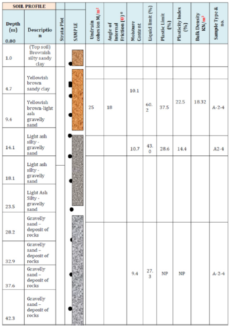
The data from the soil sampling, vane shear test laboratory test was carefully evaluated, for the determination of the stratification of the underlying soils, the evaluation uncovered a primary, brownish sandy clay layer. The investigation disclosed that the soil deposits within the depth explored are characterized by near-surface deposits of firm brownish sandy gravel of high strength with a very insignificant presence of clay of moderate compressibility of about less 0.33% overlying a stiff sandy gravel. The relevant index and engineering properties are stated below (Table 3).
Estimation of Bearing Capacity/Foundation Recommendation
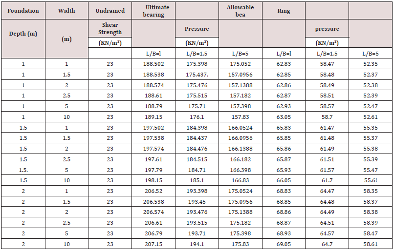
The ground investigation was conducted with the principal intention to determine the prevailing subsoil conduction at the site and also to provide foundation recommendations. The investigation uncovered, within the depths explored the existence of sandy gravelly material mixed with a mild amount of clay up to about 9.4m while a firmer sandy gravelly material precedes from there. Construction work involving excavation for deep-foundation is best carried out during the dry season especially in geographical zone of high intensity of rainfall. However, the construction programmed may demand that excavation work is carried out during the wet season. In this case, precautions should be taken to prevent the softening of the foundation soil and Engineering Properties. The investigation reveals that within the depth explored, the strata sequence from the boring is confirmed by the cone soundings and by visual inspection. A layer of silty clay of substantial thickness overlies fine gravelly clay. The index and engineering properties of the soil deduced from the laboratory and field tests were evaluated to produce ranges of soil parameters for the design of the foundations. The bearing capacity estimation has been limited to a foundation depth of 2.0m for BHl - 4 and 1.75m for BH5 respectively. The shear strength parameters used for the analysis is shown in Table 4.
The static bearing capacity was computed using Terzaghi bearing capacity factors: Gross bearing capacity. The conventional method of foundation design is based on the concept of bearing capacity or allowable bearing pressure of the soil. The bearing capacity is defined as the load or pressure developed under the foundation and in the superstructure supported on the foundation. Damaging movements may result from foundation failure or excessive settlement, the two criteria used in the design of foundation, therefore, are:
a. Determine of bearing capacity of soil and the selection of adequate factor of safety, usually not less than 2.5./
b. Estimating the settlement under the expected load and comparison with a permissible settlement. Choice of parameters
In clays, the ultimate bearing capacity of spread foundation is calculated using total stress parameters. This gives the end-ofconstruction case, which is the worst-case condition and allows the design to be based on undrained shear strength tests. The bearing capacity analysis for the underlying soils is limited to the nearsurface sandy clay and sandy gravelly materials at the respective depths of samples. In general, the sandy clay is partially saturated and when tested in unconsolidated and undrained conditions, exhibit both cohesion and angle of internal friction for its shear strength characteristics. However, the frictional component of shear strength is neglected for the clay encountered within normal founding depths for foundations when estimating ultimate bearing pressure for clay. Undrained cohesion of 23kPa and angle of internal friction of zero are adopted for the bearing capacity analysis. The cone penetrometer test results showed that the penetration resistance increases with depth. It is therefore advisable to locate the foundation of the structure for BH1 -2(1.75 - 2.0m) depth and BH3-5 at 1.50 - 1.75m with their respective allowable bearing capacities stated above. This would give safer design bearing capacity.
Data analysis and Results from Seismic Refraction Method
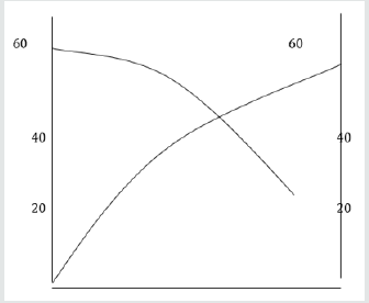
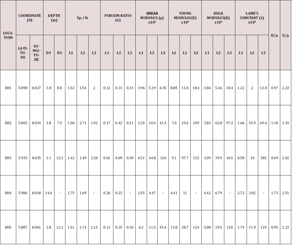
The field data that comprises travel times and offsets were tabulated and the graph of travel times T against offset x plotted for each data point is made up of P and S wave travel times (forward and reverse) they were all manually plotted. A typical T-X plot for the area is shown in Figure 2, while Table 5 shows the Elastic parameters: shear modulus (N) bulk modulus (K), Poisson ratio (σ), young modulus and lame constant (λ) were calculated using the relations documented earlier and the average value of density of sedimentary rock as 2,670kg/m3 Gibbs, 1977.
The results show that shear modulus of the first layer at all the traverses ranges from a minimum of 2.56 x 10⁸ (N/m2) obtained at traverse (4) to a maximum of 6.20 x 10⁸ (N/m2) obtained at traverse 5. The second layer had a minimum of 4.47 x 10⁸ (N/m2) obtained at traverse (4) and a maximum of 44.80 x 10⁸ (N/m2) obtained at traverse 3. In the third layer, a minimum of 10.00 x 10⁸ (N/m2) Shear modulus was obtained at the fourth traverse while the maximum value of 45.40 x 10⁸ (N/m2) was obtained at the fifth traverse. The bulk modulus of 3.09 x 10⁸ (N/ m2) was minimum at traverse one in layer one, while the maximum value of 5.88 x 10⁸ (N/m2) was obtained at traverse 5. In layer 2, bulk modulus was minimum at traverse 4 with a value of 5.46 x 10⁸ (N/m2) while a maximum value of 62.80 x 10⁸ (N/m2) was obtained in traverse 2. In layer 3, bulk modulus was minimum at traverse one with a value of 18.40 x 10⁸ (N/m2), while a maximum value of 453.00 x 10⁸ (N/m2 was obtained at traverse 3. The value of Young’s modulus also varied from one traverse to another, at layer one the minimum value of 6.41 x 10⁸ (N/m2) was obtained at traverse 4, while a maximum value of 13.80 x 10⁸ (N/m2) was obtained at traverse 5. In layer 2, a minimum value of young modulus of 11.00 x 10⁸ (N/ m2) was obtained at traverse 4 while a maximum value of 97.70 x 10⁸ (N/m2) was obtained at traverse 3. In layer 3, a minimum value of young modulus of 18.40 x 10⁸ (N/m2) was obtained at traverse 1 while a maximum value of 322.00 x 10⁸ (N/m2) was obtained at traverse 3.
Lame constant also shows a lot of variability along the traverses and layers. In layer 1 traverse 1 a minimum value of 1.22 x 10⁸ (N/ m2) was obtained, while a maximum value of 8.58 x 10⁸ (N/m2) was obtained in traverse 3. In layer two a minimum value of lame constant of 2.00 x 10⁸ (N/m2) was recorded at traverse 1, while a maximum value of (55.90 x 10⁸ (N/m2) was recorded at traverse 2 in the third layer, the value of lame constant was minimum at traverse 1 but maximum at traverse 3 with the values of 13.80 x 10⁸ (N/m2) and 382.00 x 10⁸ (N/m2) respectively.The value of Poisson ratio was minimum at traverse 3 with a value of 0.01 while it was maximum at traverse 4 with a value of 0.25. In the second layer, the value of poison ratio was still minimum at traverse 3 with a value of 0.09 while the maximum value of 0.42 was obtained at traverse 2. In the third layer, the lowest value of passion ratio of 0.23 was obtained at traverse 5 while the maximum value of 0.38 was obtained at traverse 3.
Concluding Remarks
Arising from the values of elastic parameters obtained from the study, it is clear that soils/rocks in the area require a large amount of force before a unit area can be stressed, the soils/rocks in the area are rigid and consolidated and are suitable for engineering construction work (buildings, roads etc). From the stand point of geotechnics, the analyzed samples from the bores revealed that the site is overlain predominantly with lateritic clay and stiff clay gravel sand of intermediate plasticity, from the depth of 1.75 m a good stratum for the proposed foundation was encountered. The foundation should be placed at 1.75- 2.0 m for BH1-4 with a spread footing incorporated with pad foundation. Field and laboratory investigation show that the surface is underlain by over consolidated sandy gravely materials of moderate compressibility underlying a stiff sandy clay. The allowable bearing capacity profile of the sub-surface shows good bearing capacities characteristics (1.5m: 467KN/m2) settlement predictions based on a loading of 100KN/m2. The cone penetrometer test results showed that the penetration resistance increases with depth. It is therefore advisable to locate the foundation of the structure for BH1 - BH2 (1- 75 2.0m) depth and BH3 - BH5 (1.50 - 1.75m) with their respective allowable bearing capacities stated above.
Comparatively, the seismic refraction method and Geotechnics gives similar results as both methods allude to the fact that the study area has a good bearing capacity. The cost of foundation failures is high and with increasing development on marginal lands and infill sites, it is expected problems will continue unless research is undertaken to develop superior and simpler approaches to foundation design and construction. There is a need for further research and guidance on isolation methods, which eliminate the characteristics of poor soils, and superior foundation systems, which are more resistant to frost damage. The modulus of elasticity or Young’s modulus of a soil is an elastic soil parameter most commonly used in the estimation of settlement from static loads. Young’s soil modulus, Es, may be estimated from empirical correlations, laboratory test results on undisturbed specimens and results of field tests. Laboratory tests that may be used to estimate the soil modulus are the triaxial unconsolidated undrained compression or the triaxial consolidated undrained compression tests. Field tests include the plate load test, cone penetration test, standard penetration test (SPT) and the pressure meter test.


No comments:
Post a Comment
Note: only a member of this blog may post a comment.