Lupine Publishers| Journal of Robotics & Mechanical Engineering
Abstract
Magnetic lead screw (MLS) is the upcoming alternative technology to conventional lead screw technology in modern engineering. MLSs use the principle of magnetic levitation for achieving the linear motion of the nut by converting the rotary motion of the screw. The advantage of magnetic levitation in the MLSs eliminates the contact between the screw and the nut by resulting in zero contact force, longer life with less operational maintenance and costs. This review presents the advancements in the Magnetic lead screw technologies which elaborate the design parameters, manufacturing procedures, and areas of applications of the MLS.
Introduction
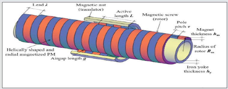
Lead screw has a wide range of applications in the industrial sector ranging from conventional lathe machines, servo motors to wave energy conversion systems. The recent advancements in the lead screw technology for converting the rotary motion to linear motion and vice versa include the development of contactless Magnetic Lead Screw (MLS) technology. The construction of MLS consists of several helically cut permanent magnets (PMs) attached to the outer surface of the screw and the inner surface of the nut. The working principle utilizes the magnetic levitation in between the screw and the nut, such that due to the helical cut of the PMs the rotating motion of the screw results in achieving the lead for the nut as shown in Figure 1. The performance of the screw depends on various design parameters, methodologies, and the alignment of the magnetic field which causes the translatory motion for the nut (moving body).
Design Parameters
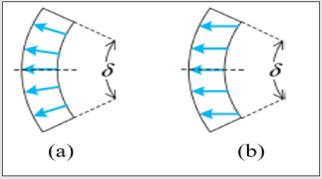
The design parameters which influence the performance rate of the MLS are the Rotor Radius, Translatory Radius, Permanent Magnet Width [1], Permanent Magnet Thickness, Air Gap, Force Density, and Pole Pitch (Pitch between two adjacent poles) [2]. The parameter force density defines the ratio between the thrust force on the screw to the total volume of the MLSs permanent magnets and the Rotor radius. It is a significant parameter that affects the air gap between the screw and the nut to maintain optimal magnetic flux for achieving the linear motion. Zhu et.al [3] mentioned a significant increase in thrust force and a decrease in force density which is observed with a change in rotor radius. The thrust force increases with an increase in magnetic thickness and width. Gao et.al showed the the usage of parallelly magnetized permanent magnets results in distortion of air-gap flux density and decrease in average thrust force and torque values, whereas the radially magnetized permanent magnets resulted in smooth air gap flux density and thrust forces [4]. The difference between the parallelly magnetized and radially magnetized magnetic fields is shown in Figure 2.
Few More Designs
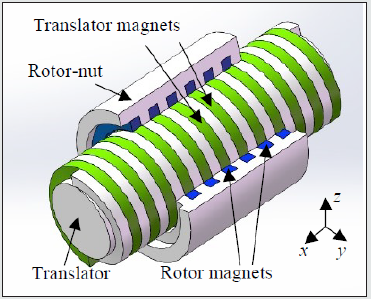
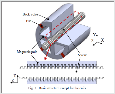
Few more designs are shown in Figure 3 where a single helix magnetic lead screw system [5] is proposed for a wave energy converting system and a magnetically levitated lead screw system [6] is proposed to eliminate the number of magnets by using a coil in between the two adjacent magnets.
Conclusion
This review reports the advancements in the Magnetic lead screw technologies by highlighting the design parameters, design methodologies of various types of Magnetic lead screw mechanisms. The Magnetic Lead Screw is more advantageous compared to Conventional lead screw mechanisms for its wide range of applications which utilizes a non-contact type of actuation.
Read More About Lupine Publishers Journal of Robotics & Mechanical Engineering Please Click on Below Link: https://robotics-engineering-lupine-journal.blogspot.com/


No comments:
Post a Comment
Note: only a member of this blog may post a comment.