Lupine Publishers| Journal of Robotics & Mechanical Engineering
Abstract
This paper describes the design principles and manufacturing techniques behind the construction of a life-size 4 degree- offreedom robot bird tail that mimics the pygostyle articulation of a 2.4-meter wingspan eagle bird. The tail provides for elevatorpitch and rudder-yaw control as well as a significant degree of lift that supplements the lift from the main wing. The tail is an articulated feather-like design that is modelled on the pygostyle of a real eagle bird. The design was based on (i) research into bird anatomy from avian anatomy books and (ii) studying slow-motion eagle flight manoeuvres from YouTube video clips. Future work concerns experimental work into validating the mechanics and aerodynamics of its design together with reduction of its weight.
Keywords: Biomimicking Eagle Bird Tail; Feather-Skeletal Accurate Bird Tail; Morphing Robot Bird Tail; Robot Bird Yaw-Pitch Control; Robot Bird Tail Manufacturing Process; Robot Feather Fanning Mechanism; Robot Pygostyle
Background to the Tail
This paper describes the tail design principles of a bird robot that forms one component of a longer-term plan to build a 2.4-meter wingspan biomimicking eagle bird robot that can fly similar to an eagle. The design principles are described in limited detail due to the page constraints of this paper. The robot is considered a “big bird” robot as distinct from robots that emulate insects or hummingbirds. This eagle bird robot will be able to fly and hover by flapping its wings. Flapping flying robots are not new since such robots, known as ornithopters, have been in existence for more than a hundred years together with, recently in the last few years, much improved ornithopters such as the ingenious Festo Smart Bird, [1]. However, these big bird ornithopter robots cannot hover and neither can they morph their wings from flying mode into a closed compact body shape format and vice versa. What is new about the robot and, in particular, the tail system described in this paper is that it is designed to mimic accurately the feather and skeleton system of an eagle bird such that it can hover as well as close its main wings and tail into a compact shape. As such the robot will have 12 feathers in its tail and 24 feathers in each of its two main wings thus the robot will possess a total of 60 feathers. Furthermore, its main wings will have wrist bending and forearm rotation joints. The main wing up-down flapping articulation mechanical power pectoralis major and supracoracoideus biomimicking muscles will come from two pairs of ultra-low impedance muscle actuators that are work-inprogress. The 12-feathered tail, which is the subject of this paper, is able to, (i) open and close its feathers in a fanning motion, (ii) rotate the pygostyle about an athwartships axis to give flight pitch control, (iii) rotate the pygostyle about a longitudinal axis to give yaw control that is in conjunction with pitch control and, (iv) shift the feathers left and right to give some control of flight balance about the longitudinal axis in conjunction with the pitch and yaw control.
Robot Tail Overview
The design of the tail is largely based on (i) YouTube slow motion video clips of eagles, e.g. [2], and (ii) avian anatomy and physiology described in an illustrated book, entitled, “Manual of Ornithology: Avian Structure and Function” by Proctor & Lynch, [3]. In anatomical terminology, tail feathers are called retrices (singular: retrix) and are mounted on the pygostyle and, in turn, the pygostyle is mounted on the jointed caudal vertebrae, that is at the end of the backbone. The pygostyle, via the muscle-actuated caudal vertebrae is given up-and-down, side-to-side, and twisting motion. The feathers are given opening and closing motion by muscles mounted on the pygostyle. The robot tail design, shown in a photograph, Figure 1 and schematically, Figure 2, is designed to emulate almost all of the motions of a real bird tail.
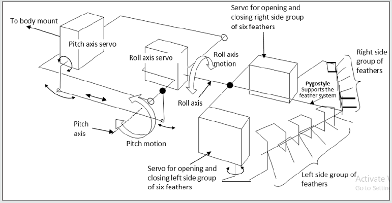
The tail, [Figure 2], is actuated by four Futaba BLS152 servos that control its joints to give (i) pitch control (quantity 1 servo), (ii) roll control (quantity 1 servo), (iii) independent left-side group of six feathers control of opening and closing, (quantity 1 servo) and (iv) independent right-side group of six feathers control of opening and closing (quantity 1 servo).
Figure 1: Photograph of the robot eagle bird tail. It consists of (i) 12 feathers, (ii) a pygostyle that holds and articulates the feathers to open and close, (iii) an articulated servo-driven pitch axis that drives the pygostyle up and down and, (iv) an articulated servo-driven roll axis that rotates the pygostyle.
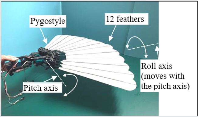
Figure 2: Schematic diagram of tail actuation system and pygostyle showing pitch and roll axes plus left and right side feather group servo actuated systems.
Feather Opening and Closing Action
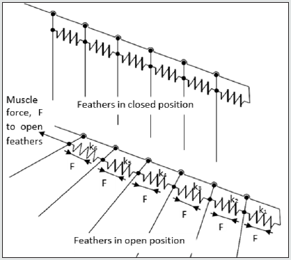
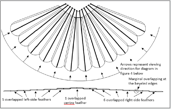
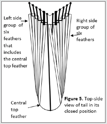
Figure 3 shows a top view of the tail in its open position and Figure 4 shows a view along the axes of each feather viewed from the rear. It can be seen from Figure 4 how the feathers marginally overlap to give a wind proof surface. There are 12 feathers that make up the tail. Six of these feathers make up the left side group and one of these six is the central feather that is the topmost feather of all the 12 feathers. The remaining six feathers form the right-side group. Note, importantly, that all flying feathers on a bird move to a lower position as the feathers move away from the centerline of the body. As an approximation, the tail in its closed position, the outermost left and right feathers extend outwards from the center by 60° when they open. Similarly, the 2nd pair of feathers, working in from the outermost pair, extend by 50°, the 3rd pair by 40°, the 4th pair by 30°, the 5th pair by 20° and the remaining innermost pair by 10°. This is an approximation because the feathers are directed slightly towards the center in the closed position, so the feathers actually extend more than 60° for the outermost pair and likewise more than 10° for the innermost pair. However, the approximation gives the reader an idea of how adjacent feathers must angularly interact in order to produce the correct fanning action when opening and closing. For example, we will assume that the outermost feather is driven by a servo. The servo will extend this outmost feather by 60° from the closed position to the open position. We will call the outermost feather, feather 1; the next inner feather, feather 2 and so on. Feather 1 should extend feather 2 by 50° and feather 2 should extend feather 3 by 40° and so on. Thus, there needs to be a discrete angular mechanical gear ratio between each feather working from feather 1 to feather 6 as follows; 6:5, 5:4, 4:3, 3:2, and finally 2:1. Figure 6 shows how this interactive set of gear ratios could be achieved using an interconnected serial spring system that could be physically enabled by biological tendons. This is probably the mechanism for a biological bird.
Figure 4: Rear view of all 12 tail feathers in open–tail position viewed from the rear in an arc in directions as shown above in figure 3. Note that the feathers overlap marginally at their edges by 1cm that matches the beveled edges.

Figure 6: Method for obtaining correct fanning angle ratios. Tensile forces in equilibrium. Thus, arrange spring stiffnesses, k1, k2, k3, k4, k5 and k6 to give required deflection in order to required feather angle change during fanning.
Design and Theory of the Pygostyle Opening and Closing Mechanism
Figure 7, photographs (a) and (b), show top- side and underside views respectively of the pygostyle opening and closing articulating mechanism with the feathers in the open position. Conversely, Figure 8, photographs (a) and (b), show the feathers in the closed position.
The kinematic theory behind the serial articulating link mechanism is illustrated in Figure 9 which shows two adjacent feathers, feather 1 and feather 2, with rotating joints located at a1 and a2 respectively. Feather 1 is considered the driver feather and feather 2 is considered the driven feather. The reason for this arrangement is that feather 1 is further out from the center of the robot and the outermost feather is driven by one of the pygostyle servos. A feather that is further out drives the next inner feather through a smaller fanning angle than its own, 60° to 50° or 50° to 40° and it is always good practice for an actuator to drive a reduction ratio rather than vice versa because the inertia seen by the actuator is reduced and the actuator displacement is increased thus greater control precision is achieved. The distance a1a2 is set by the feather pitch and is equal to 18mm. Suppose that the required reduction ratio between feather 1 and feather 2 is 0.421. Meaning that feather 1 is the driver and moves by 10° and thus feather 2, the driven, is required to move by 4.21° in order to give an effective fanning operation. We now set the lengths of links a1c1 and a2c2 to be 7.89mm and 18.74mm respectively, thus 7.89/18.74 = 0.421. Both feathers are now temporarily fixed in their mid-range positions, a1b1 and a2b2. Two links are generated for each feather, a1c1 and a2c2 and these links are of lengths 7.89mm and 18.74mm respectively as calculated just previously. These links are then set mutually parallel and a link, c1c2, generated between them where the link is of such a length that angles a1c1c2 and a2c2c1 are both 90°. The length of c1c2 is calculated as 14.36mm. The links a1c1 and a1b1 are now welded together at a1 and likewise the links a2c2 and a2b2 are now welded together at a2. Feathers 1 and 2 may now be released from their temporarily fixed positions and the mechanism is now serviceable over a limited angle range either side of the mid-range position meaning that it will give good linearity and an accurate gear ratio for a limited range of angles. Figure 10 shows relationship between feather 1 and feather 2 angles over +/-30° angle change of feather 1. Figure 1 shows that the error of the link mechanism stays less than 5% over a range of 60° range of the input driver crank angle. Such an error is considered acceptable and is seen as accurate because the feathers remain marginally overlapped without any gap appearing. Figure 11 The link geometry has been worked out for each feather-to-feather connection. A problem that occurs is in implementing the link mechanism such that it is highly compact. This took many hours to calculate and design with many iterations.
Read More About Lupine Publishers Journal of Robotics & Mechanical Engineering Please Click on Below Link: https://robotics-engineering-lupine-journal.blogspot.com/

No comments:
Post a Comment
Note: only a member of this blog may post a comment.