Lupine Publishers| Journal of Civil Engineering and its Architecture

Abstract
Lateral buckling analysis of fixed rectangular plates under the lateral concentrated load is an interesting problem. However, there is not a determined equation to calculate the critical elastic buckling strength of such plate. This paper presents the equations of the previous studies by Cheng and Yuan and analyzes the critical buckling strength of the plate calculated by finite element method (FEM). Finally, discussion and suggestion on the trends in developing critical elastic buckling formula for such plate are made.
Short Communication
Rayleigh-Ritz method is commonly used energy method to calculate the elastic buckling strength of a plate Qu [1]. The total potential energy of a structure is π = U + W , where U is the buckling deformation potential energy and W is the external potential energy. The critical buckling strength of a structure can be calculated once . For an end-fixed rectangular plate subjected to a concentrated load, the mechanical diagram is shown in (Figure 1). The buckling deformation potential energy of the plate can be determined as:
Figure 1: Mechanical diagram of the plate.

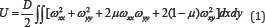
Where D = Et3 /12(1 -μ2) is the buckling stiffness of the plate; E and t is the elastic modulus and the thickness of the plate, respectively; n is Poisson's ratio of the material used for the plate. ρ is the buckling deformation function, and ωxx,ωxy,ωyy are the partial derivatives of the buckling deformation function.
The external potential energy of the plate can be calculated by:
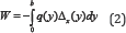
Where q is the lateral concentrated load and Δx (y) is the out- of-plane displacement of the plate caused by the buckling of the plate. It can be found that the critical buckling strength of the plate is determined by buckling deformation function. Therefore, it is important to assume a feasible buckling deformation function for the analyzing plate. Cheng [2,3] proposed the buckling deformation function as:
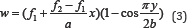
Yuan [4] modified the buckling deformation function of Cheng (1988), and given it as:
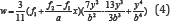
Where f1 and f2 are unknown variables to describe the various types of the buckling deformation function, thus the critical one could be found in these functions. Through case studies conducted by Yuan [4], the critical results calculated by Eq. (4) were lower than the results calculated by Eq. (3). Thus it was concluded by Yuan [4] that the Eq. (4) was more accurate for determining the critical buckling strength of the plate. However, Yuan [4] proposed another buckling deformation function as:

With developing of the computer-aided calculating method such as finite element method (FEM), the buckling modes of the analyzed plate can be depicted more visually. In this paper, the FEM model for the analyzed plate is generated by the FEM software ANSYS 12.0. A target plate is selected with a constant value of 2.7 m in height, and the elastic modulus of the plate is 206 GPa. The width of the plate is changing from 1.35 m to 3.6 m, and three cases with height-to-width ratio 2.0, 1.5 and 0.75 are analyzed. The thickness of the plate is 10 mm, 12 mm and 14 mm. Eigen value buckling analysis of these FEM models is conducted by Block Lanczos method. The first 5 orders of the buckling modes of these plates are generated, and the cases of α=2.0, α=1.5 and α=0.75 with 10 mm in thickness are depicted from (Figures 2-4). The critical strength of these plates for which calculated by FEM are shown in (Figure 5).
Figure 2: Buckling mode of the plate with ɑ=2.0.

Figure 3: Buckling mode of the plate with ɑ=1.5.

Figure 4: Buckling mode of the plate with ɑ=0.75 and t=10 mm.

Figure 5: Relationship between the critical strength and of and the � Jiang et al. [3].

Discussion and Suggestion
As shown in (Figures 2-4), it can be found that the consequence of the buckling modes is moved by changing the height-to-width ratio of the plate. High-order buckling mode may be occurred in the plate with lower height-to-width ratio. According to the studies conducted by Cheng and Yuan, only two variables were in their equations, and the cosine function and polynomial function were used to describe the buckling modes of the analyzed plates. However, two variables might not be used to present the high-order buckling mode of half-waves more than three. Such functions limit more degree of freedom (DOF) of the plate, and the critical buckling strength calculated from such functions is larger than the correct value.
Thus this paper suggests the buckling deformation function as follow:

Such function should be following the boundary conditions of the plate, and they are:

The Eq. (6) combines the double series function derived by Navy, and the single series function derived by Levy, and aims to find the most proximal buckling deformation function for the critical buckling mode of such plate.
Read More About Lupine Publishers Journal of Civil Engineering and its Architecture Please Click on Below Link: https://lupinepublishers-civilengineering.blogspot.com/
No comments:
Post a Comment
Note: only a member of this blog may post a comment.